CNC in the (Model Engineers’) Workshop

Part 15

Instalment 15 of CNC In The (Model Engineers’) Workshop was published in the July 2014 issue of Model Engineers’ Workshop (issue 217).
This month saw the continuation of the project to make an Etch Folder.
This instalment contained information about machining the clamp bar with its stepped face and angled nose, using parameters to simplify the programming; and including an organised list to keep track of the CP and generate the G code commands required to machine the periphery.
Nothing if not ambitious...
MEW Issue 217 : July 2014
Programs
To ease the load on your tired fingers, here are the programs shown in this instalment:
In each program, the initial comments and initialisation block commands have been added to what appears in the magazine, and there are additional comments throughout the programs to help you understand the flow of the program and the purpose of each section. That would all be too much to add to the pages of the magazine. If you have been following the series, you should know that these things all need to be in your completed programs, but downloading the code from this website will give you the complete programs.
Page 55, Clamp plate profile - includes the steps, but does not include the angled nose because that requires a different tool.
The spreadsheet is designed to illustrate the beginnings of a method, but is not an infallible finished tool. It’s purpose is to suggest that if you are organised it is a relatively easy mechanical task to generate G code commands for the ‘plan view’ shape of the periphery. As we will discuss in an upcoming instalment, there are several viable G code generators, of greater or lesser sophistication, and costing more, or less. Note that I am not suggesting there is any real correlation between cost and effectiveness...
This is an important topic, though, because we will soon find we cannot manually generate G code for complex curves and some other features. The spreadsheet simply demonstrates a method. Feel free to experiment with the spreadsheet, but please don’t expect it to be infallible or to cope with anything other than the kind of straightforward lines-and-curves paths like the one in the example.
The file is a ZIP file, saved in .xls format, so should be openable in most spreadsheet programs. It has 6 pages, organised in pairs. In each pair, the first page contains co-ordinates, manually entered G1, G2 or G3 codes to indicate the type of operation required at each stage, and a set of columns in which the spreadsheet calculates the X, Y and (where required) I and J values. The second page in the pair looks at the first page and concatenates the G command and the values, and produces a string of text for each command. That “program” can be exported as a text list and used in a text editor or word processor where the program can be completed, or where it can be copied and pasted into a program.
It’s experimental, but I did use this to produce the text shown in Table 3 of page 54.
If you select ay of the text on the second page of a pair of sheets, then look at the formula bar , you will see the formula I used. I am sure it could be improved...
The pair of pages I used to prepare table 3 are entitled Roughing and Roughing Commands. I did not include the point X-3.1 Y-9.1 at the start of the arc, or X-3.1 Y-6.1 (centre of the arc) because I mentioned in the text (page 54, column 3, last paragraph, beginning “Assuming the CP has already been placed at that point...) so the first executable command would be the G2 for the entry curve. I suppose I could have included that; but I didn’t. Sometimes the sun shines, and sometimes it doesn’t...
Please don’t get hung up on this spreadsheet, or the method. It’s just an illustration, and not particularly important, at this stage. What is important is an organised approach. That will save tears later.
Page 54, G Code Generator Spreadsheet
If you experience any problems downloading or unzipping these files, please let me know.
I am slightly worried by the double use of the full stop in the filenames. It may have a troublesome effect on Windows computers. On the other hand, no-one has yet complained about previous files which have exactly the same filename structure.
Sloping nose
I suggest cutting the sloping nose using a large countersink. That’s far from an ideal tool, for machining aluminium, although I did get decent results. A much better tool is a proper 90 degree Vee tool, and we will meet one of those in an episode coming up shortly. However, most folks are likely to have a countersink, so that’s a viable way of doing the job, for now.
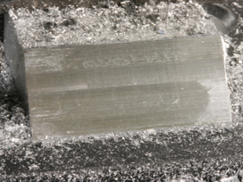
Remember that the tool angles for machining steel are not ideal for cutting aluminium (in fact they are a mile out), so use plenty of carnauba wax lubricant. I’m using an old tin of Simonize (with the price marked in shillings and pennies), applied using a toothbrush (34p from Sainsbury’s), and the results are as shown in photo 97 on page 52 of issue 217. Tolerably good. A proper Vee tool designed to machine aluminium gives a finish which is in a whole different league (as I’ve said before, when using tools desinged to cut aluminium).
Note that upcoming projects include a couple which require significant machining of aluminium, so I would encourage you to spend a little and get some really effective cutters designed for machining aluminium. It makes a world of difference. Or stick to those old steel cutters rumbling around in your bottom drawer; the ones with the chipped edges.... seriously; if you have not experienced machining aluminium with a purpose-designed cutter, you have missed a treat.
Alternative loops
Near the end of page 54, and again in the first column of page 55, I suggest there are other ways of positioning the CP when machining the steps. What I have in mind is the way the loops are set up.
Before using the loop for the first time, there’s a choice between:
Outside the loop:
setting the initial depth of cut (#41 ) to 0
then, inside the loop:
subtracting the depth of cut from the Z height (to lower the CP)
then machining the step at that new height
or
Outside the loop:
setting the initial height to a value one step lower (#41 = -1).
then, inside the loop:
machining the step at the current height, then
subtracting the depth of cut from the Z height (ready for the next time around the loop)
The difference is that in the first method, at the end of the loop Z is at the depth of the current step, while, in the second method, Z is at the depth of the next step.
In the example, I have chosen the first method:
#41=0, then
subtract the depth of cut from the Z height (to lower the CP)
then machine the step at that new height
In many ways, which method you choose is a programmer’s philosophical question, and there are sometimes advantages in one or other choice, depending on exactly what is being done inside the loop (especially if it a more complex series of operations than shown in the example).
For now, the point is that there is usually more than one way to programme a sequence of instructions. I can show you one way, but you might prefer another. Who is right? Assuming there is such a thing as a right answer (and the judgement is often simply between degrees of elegance in the finished code), any machining sequence which guides the CP along an appropriate path is “right”.
I might judge between solutions by asking the question: which program is easiest to understand, in 6 months’ time?
Answers on a postcard...
Figs 80 and 81
Lest you should think there’s something amiss, figs 80 and 81 are associated with another workpiece. They are intended to accompany the debugging discussion, and were deliberately chosen because they are not a part of the Etch Folder. Works for me, if no-one else, but I would not wish to leave you confused.
Newsletter
We’ve reached a critical mass of subscribers, so there may be a Newsletter sometime soon-ish.
It depends on whether I can work my way out from a very busy workshop.
Download the article here