CNC in the (Model Engineers’) Workshop

Part 8

Instalment 8 of CNC In The (Model Engineers’) Workshop was published in Model Engineers’ Workshop dated December 2013.
This continued the stages in making the vice stop.
A handy item in its own right, making the stop gives practice in facing, creating stepped faces, and locating the CP by Touching Off in various ways.
MEW Issue 210 : January 2014
The embellishment
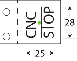
It’s relatively easy to embellish your work, and the vice stop looks all the better for the lettering added to its outside face.
The letters were created using techniques as yet unexplained in the series. We will get to all of that soon enough, but, in the meantime, the lettering was created in Vectric software, then tweaked a little by extending the top of the T of STOP.
It was saved as a Mach3 file, opened in Mach3, and machined from there.
Because the series has not yet reached the point at which readers will know how to do all that, the file is available for download,
Click HERE to download the file.
(It’s a ZIP file, so you will need to unzip it once it has downloaded.)
The instructions in the magazine, on page 72, tell you all you need to know to use the file to machine the logo.
The article mentions a speed of 5000rpm, but the file actually uses S12000 to set the speed to 12000rpm. On most machines, its a case of “you’ll be lucky”. Set the speed manually, to the top speed of your machine, and leave it at that. It should work fine.
No guarantees, of course.
The article also mentions a feed rate of 50mm/min. The file actually uses a top feed rate of 25mm/min, because I’m being cautious.
Once loaded, do as you should always do, and check the Toolpath to make sure all is as expected.
Set the CP to the centre of where the logo should go (see the article for more details) and with Z0 at the top surface of the work.
Run the program in the air, first, by taking the CP clear, above the work (say 10mm or so - but make it a distance you can remember easily) and set Z to zero there. Run the program and watch what’s happening.
If all seems ok, and with Z 0 still up in the air, 10mm or so above the work (or whatever you chose) set Z to 10 there so that the CP will once again be at Z0 at the top surface of the work.
Effectively, what you have done is to displace the Z values by 10, temporarily, then removed that displacement again. That’s actually a very useful technique when carried out within a program, and we will look at that in a future instalment.
For now, enjoy watching the logo appear.
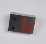
As ever, the suggested lick of paint makes all the difference to the presentation.
If you were intending to polish or grind the top surface, paint the logo first, and don’t worry too much about overspill. Let the paint dry thoroughly. The overspill will disappear as you finish the top surface.
If you are leaving the as-machined finish, you can either:
use cotton buds to wipe any overspill away; or
put a couple of strips of masking tape over the logo, run around the inside of the outlines of the letters with a very sharp knife or scalpel, apply paint, then immediately remove the masking tape; or
do much the same thing, but use Frisk paper (it’s transparent, so you can see where you need to cut, and its low-tack so it comes off very easily).
Make several stops, and paint them in different colours....knock yourself out.
If you want to change the spindle speed, you can open the program in the editor of your choice, and change the S command. There is only one, and its to be found just as the G codes begin.
You can change the feed rates by searching and replacing. I suggest you search first for F25 and change all those, then search for F10 and change those too (to roughly half the new feed rate you have chosen).
You are on your own with those changes, of course.
Download the article here