CNC in the (Model Engineers’) Workshop

Part 6

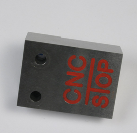
The 6th instalment of CNC In The (Model Engineers’) Workshop was published in Model Engineers’ Workshop dated October 2013. This continued the sequence of instructions for making the vice plate then moved on to the Vice Stop Block for repetition work. Both projects illustrated CNC drilling and facing.
MEW Issue 208 : October 2013
Typo
There’s an error on page 18, third column, where there are missing - signs in the code fragment. That section should read:
-----------------------------------
Using G code, the instructions for the first hole might be:
G0 Z1 (to take the drill above the work)
G0 X0 Y0 (it may already be there)
S3000 M3 (speed 3000rpm, start the spindle turning clockwise)
F150 (set the cutting feed rate)
G1 Z-3 (move at cutting feed rate down to Z-3
which is 3 units below the top surface of the work)
G1 Z-6
G0 Z1
M5 (stop the spindle if you are drilling just one hole)
-------------------------------------
This is a relatively unsophisticated way of drilling a hole, but manually typing the two commands G1 Z-3 and G1 Z-6 ensures a pause between the two, and that’;s enough to break any chips. The hole is shallow, so there won’t be much of a problem.
Doing it this way, though, simulates the action of a more capable peck drilling G code command we will use later.
If you want to investigate that now, its the G81, G82 and G83 commands, but you will need to watch what you’re doing with the G98 and G80 settings. If you are a beginner, I don’t recommend those commands just yet. The principle lying behind them is useful, though. They are “canned cycles”, effectively single commands which carry out a sequence of tasks for a specific purpose.
We will visit that notion shortly, as it provides us with a very important tool.
Download the article here