CNC in the (Model Engineers’) Workshop

Part 20

Instalment 20 of CNC In The (Model Engineers’) Workshop was published in the February 2016 issue of Model Engineers’ Workshop (issue 238),
This month saw the completion of the two-part project to manufacture a custom top yoke for the forks of a custom Harley Davidson motorcycle.
This instalment contained information about more workholding challenges; some machining techniques; and some thoughts on Wizards.
MEW Issue 238 : February 2016
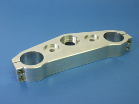
The Yoke
For those of you who don’t have your copies of MEW readily to hand, the drawing for the yoke is shown. In this instalment,as well as everything else, the recesses in the yoke were machined. It’s worth saying something a little more about the concept of Wizards, which was discussed briefly in the article.
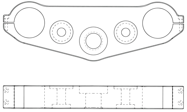
(The drawing of the yoke)
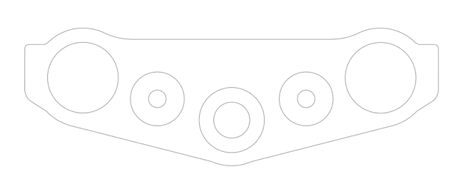
(The continuous outline and the pockets and holes)
Wizards in general
Wizards are not a new idea, of course, and I recall writing books in the 1980s explaining how to use Demons (i.e. Demonstration sub-routines) for programming in BASIC and COMAL on the old (and much loved) BBC computer. There were libraries of sub-routines for graphics programming on the Sinclair Spectrum and the Acorn Electron; and lots of similar blocks of program code on most of the other machines around in those early days. The concept is simply that of re-usable sections of code, each of which does a specific job, in a library. Written once, these blocks of code can be used many times. Extending the concept, a good subroutine encapsulates the method for doing something, but is sufficiently flexible that it can be applied to any case where that method is required.
So, for example, writing a bit of code to create a cylindrical hole 40mm diameter is useful, but will only do one job.
Writing a bit of code which creates a cylinder of any diameter (the exact diameter to be specified only when the code is used) means that, within limits set by cutter diameter and machine size, that code can be used to machine any cylindrical hole. Making the code into a subroutine means it can be called from anywhere within a program, and can be re-used as often as necessary.
That means if I have a small library (i.e. a collection) of such sub-routines, each of which allows you machine a particular type of feature, you can cut down on the raw programming you need to do to create a part. This is important and I will say more on this topic as time goes on.
These subroutines or blocks of code have been called many things, including Demons and Wizards.
In Mach3, Wizards are not quite the same thing, but are an arrangement which does a somewhat similar job. Rather than having pre-written blocks of G code, a Mach3 Wizard is a piece of software (not G code) which runs externally and creates G code as required. That G code can then be pasted into a program. There are advantages in dong things this way, and it is one way of overcoming the limitations within the structure of G code programs. It suffers from two drawbacks.
First, it is a little clumsy because it generates inelegant code. That’s not particularly important to most people, but I do like a nice bit of code...
Secondly, the way the program generator (Wizard) works is determined by the programmer and cannot be altered by the Mach3 user. That means the method is fixed by the creator of the Wizard. And that’s a problem; firstly because the method may not suit the job (entry or exit moves may be in the wrong place for a specific job, for example), and secondly because the method may not suit the way I prefer to work. That second issue was the problem with the Mach3 pocket wizard, because it plunged the cutter vertically downwards into the work whenever it increased the Z cut. My own preference is to ramp the cutter into the work while descending in Z, making a more gentle entry, before clearing the area inside the pocket. But I couldn’t alter the way the Wizard worked because the Wizard itself is a program written in Visual Basic, which generates the G code when it runs. I couldn’t alter the Visual Basic program because it was run-time code, meaning the Visual Basic program code wasn’t actually there; it was only a locked version of the code which would run but could not be edited.
Using Wizards to create the pockets
You can download a copy of the program I initially used to create the three pockets in the top of the yoke, by clicking here.
This program was created by using the Mach3 Pocket Wizard three times. Each time, the Wizard generated the G code for a specific size of pocket in a specific place. The final program contained my own initialisation commands, and a copy of the G code commands generated by the Wizard for each of the three pockets, each in its own subroutine. When the Wizard was run, the centre of the pocket was chosen as 0, 0 so that is could be used anywhere. It’s a lengthy program but the structure is quite simple.
For each pocket in turn:
move to the centre of the pocket
call the relevant subroutine
and inside the subroutine, use a G92 command to make the current point 0, 0 temporarily
use the Wizard G code to machine that pocket
use G92.1 to remove the temporary offset and restore the co-ordinates
Using a CAM program to create the pockets
A more flexible way ot create the program to machine a pocket is to use a CAM program like Cut2D or VCarve Pro. The advanatge is that there is more control over how the tool moves. So, for a pocket, you should be able to specify whether the cutter plunges into the work, and the speed during the plunge, or whether it ramps into the work, and the way in which it does that, as well as the distance over which the ramp takes place (i.e. the angle of the ramp, effectively). This makes a big difference to the way the cutter experiences the work, and removes my objection to a sudden and brutal plunge directly into the work. Maybe if you are using a 20 ton machine with a large diameter cutter and flood coolant etc you would want to plunge right in as fast as you could go, and get on with the job. Not with my mill, thanks.
A philosophical point
So; in essence; what’s the difference between using a Wizard and using a CAM program?
Actually, not as much as you might think; but more than you might expect.
They are similar in the sense that they both generate code for you.
They are different in that a Wizard is restricted to generating a block of code. If that’s all you need for the whole job, then that’s similar to what the CAM program will do, but does not include the initialisation block for the program as a whole.
If you need to create more than one feature, you will need ot assemble our own program from blocks of code generated by individual Wizards (or the same Wizard used repeatedly) so you need to create the overall framework for the program, and mechanically create then append blocks of code to create a complete program. The CAM program, on the other hand, always generates the whole program. You can use it to generate code for an individual feature, but it will output as a complete program, so you would need to edit to remove code you don’t require, then cut and paste what’s left into another program.
So; similar but different.
The CAM program will always give you the complete program ready to run. A Wizard will always give you a block of code. It’s horses for courses, as usual.
The concept of Wizards does lead to Conversational Programming, which has much to commend it; and we’ll pursue that topic shortly.
Article not yet available for download