CNC in the (Model Engineers’) Workshop

Part 16

Instalment 16 of CNC In The (Model Engineers’) Workshop was published in the August 2014 issue of Model Engineers’ Workshop (issue 218),
This month saw the conclusion of the project to make an Etch Folder.
This instalment contained information about machining the sloping nose of the clamp bar; embellishing the finished bar with a logo; and machining the knobs.
That concludes this project, and brings a short break in the series, so that the editor can print some of his backlog of articles by other authors.
MEW Issue 218 : August 2014
Programs
The programs this time are for the logo and the knobs.
As discussed on page 25 of MEW 216, the programs for the logo offer some alternatives, so take your pick.
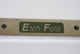
Logo
The logo is a recess with raised lettering. This is a candidate for a CAM program, and I used a drawing program to create the lettering (Adobe Illustrator) but you could just as easily use a CAD program like TurboCAD or AutoCAD, or a CAD/CAM program. Or there’s Inkscape. Output should be a DXF file, which can then be opened, or imported into, the CAM program.
I used Vectric’s VCarve Pro v6.5, but Cut2D will do the same job. The output is Gcode for your choice of CNC program (Mach3 in the articles, but it could be formatted for LinuxCNC or any other CNC program just as easily.)
A recess is just as you would expect, but in CAM terms is referred to as a “pocket”. The raised lettering within that is an “island”.
Method 1 uses an engraving cutter to do the whole job. Perfectly feasible. Book your holiday to somewhere sunny, and the program might be about half way through when you return with a decent tan. Yawn.
Method 2 clears the large areas with a 2mm end mill, then finishes the detail around the edges and within the lettering using an engraving cutter. This means a tool change (a manual change, because Vectric’s software does not recognise or operate a toolchanger), so this has to be two separate programs. It’s a faster method, though, so its well worth the effort.
The program for Method 1 is here
This program uses an engraving cutter with a 15 degree half-angle (30 degree included angle) engraving cutter with a 0.2mm tip.
The programs for Method 2 are here and here
The first of these programs uses a 2mm diameter end cutting end mill, and the second program uses an engraving cutter with a 15 degree half-angle (30 degree included angle) engraving cutter with a 0.2mm tip.
Knobs
The program segments are listed on pages 26 and 27 of MEW 216, but a complete program is available here.
As far as I can see, I have not stated the size of the cutter, in MEW 216, but it is listed in the comments within the program. It’s a 6mm end cutting end mill for aluminium. Yo already know my opinion, so I don’t need to tell you that you will get best results using a cutter specifically designed for machining aluminium. Use an “ordinary” end mill if you must, but be prepared to stand and lubricate continuously, then do some finishing by hand.
The Etch Folder has been an interesting project, and I have found it useful for working with small etches, so I hope you have not only found it a useful example which illustrates some CNC techniques, but a useful little tool in its own right.
I may say something more, on this site, about the cold enamelling method of filling the engraving. If you don’t fancy cold enamelling, just use an attractive colour of paint. It won’t be so durable, but the paint sits in a recess, so it has some protection against scuffing anyway.
Download the article here