CNC in the (Model Engineers’) Workshop

Part 11

Instalment 11 of CNC In The (Model Engineers’) Workshop was published in the March 2014 issue of Model Engineers’ Workshop (MEW 213).
This instalment considered how to use the same set of instructions to machine the same path, but in a different place each time. Subroutines and the G92 command took us to an important new level.
MEW Issue 213 : March 2014
Glorious G92
I remember the day quite clearly: the sun shone, birds sang, and all seemed right with the world (well; we can dream). 5 milliseconds after discovering the G92 command I realised the sun, moon and stars in the universe were all within my grasp. At last, I had a means of producing multiple copies of a workpiece. Load the first big sheet of material and proceed to make 50 identical copies of the essential parts for my intergalactic beam-me-up-Scotty thingy. Truly wonderful. Thoroughly recommended; and lots of fun.
Interesting thing, though. I also discovered the G52 command which describes itself as a “temporary work offset”. So what’s the difference? Not much. So read the instructions in the Mach3 manual (v1.84, section 10.7.16) and note that G92 and G52 are essentially the same thing, and must not be in operation at the same time. One significant difference is that with G92 you can take the CP to a point then tell Mach3 what co-ordinates you want that point to have. With G52 the recommended method is to take the CP to a position then tell Mach3 the offsets required to add to the existing co-ordinates to get the temporary co-ordinate values you want the point to have. So G52 X3 Y10 means take the existing co-ordinates and add 3 to X and 10 to Y to get the new, temporary, co-ordinates for X and Y. Handy? Not really.
In fact, this is typical of pairs of commands we will come across, where one version (presumably the earliest developed version) makes us do the mental arithmetic, while the other version makes Mach3 do the arithmetic.
My advice is to stick to G92 and ignore G52.
G52 is not compatible with other systems such as LinuxCNC, so that perhaps tells us something.
Subroutines
Subroutines are one of the key structural elements which we can use when writing programs. Despite their simplicity, they really are a fundamental and very powerful tool.
In the Clock Stand Seat example in this MEW instalment, we meet subroutines in their basic form, and will develop their use over the forthcoming Etch Folder project in the next instalment or two. For now, the basic structure and straightforward use of subroutines takes us a big step forward.
The basic method of using G92 and G92.1 within a subroutine is as shown at the top of page 11 of MEW 213.
Use G92 to make the current point X0 Y0
Perform some movements of the CP
Remove the offsets using G92.1 to restore the original co-ordinates.
Notice my comments about Clean Code. You can think of this as meaning a subroutine (or a block of code) which behaves in an absolutely predictable way. In practice, for a subroutine, that means we have a precise specification for where the CP will be on entry; and a precise specification of where the CP will be on exit; as well as being able to predict any other effects the subroutine will have.
Note that this does not mean we always need to know the actual co-ordinates on entry and exit. In many cases it is enough to know what will happen to the CP wherever the CP happens to be positioned when we call the subroutine. In fact, it is most useful if a subroutine will do a predictable job without depending on the CP being at a particular position. That gives us flexibility to develop general purpose subroutines, or to re-use subroutines from one program within another program. That’s a theme you will see throughout the next few instalments in MEW.
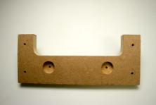
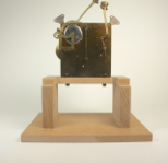
Clock seat programme
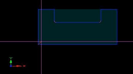
As an exercise, you might like to create a subroutine which will take the CP around the periphery of the Clock Stand Seat shown in fig 56 (page 10 of MEW 213). You will need one extra dimension for that figure: the distance from the bottom of the seat to the bottom edge of the cut-out, which is 50mm (see figure below) .
You can also download the fully dimensioned figure here).
Why G code?
From my memory of the early days, this story rings true:
Look at the post by “awander” dated 06-15-2012, 10:54pm, here

You can ignore the holes, at this first stage. Just produce a program which uses a subroutine to machine the periphery using an 18mm cutter. In the subroutine, don’t refer to Z at all. That way, you can set Z outside the subroutine, in the main program, and the subroutine should machine the periphery at that Z height. So Z is your depth of cut.
That also means you can take more than one bite. Set Z to an initial value (say 10mm) and use the subroutine. Then set Z to the next depth of cut (say 20mm, to allow a small overlap clear of the bottom of the work) and call the subroutine again. It should do the same thing, but with a greater depth of cut.
A 10mm bite might be too much for your machine, in which case you can use smaller depths of cut, but use the subroutine more often.
This is a theme we will develop in the next instalment in MEW.
Do remember, though, that if you are actually trying this out, the example assumes:
the material is 18mm thick, and
there is packing under the material, to allow the cutter to descend
at least 2mm below the bottom of the material before hitting the
table.
The Toolpath should look like this:
If you tilt it, you should be able to see two cuts (or more, if you have used a greater number of smaller cuts).
You will find a completed example of the program, here.
For comparison, there is also an example of the same program without subroutines, here.
Now add a subroutine to machine the two pockets for the seat bolts (at X58 Y30 and X162 Y30). Ignore the small centre holes.
Now your program should be able to machine the whole periphery, and create the two pockets.
The Toolpath should look like this:
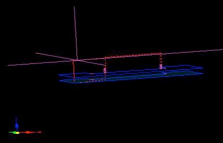
That’s a tilted view, showing the two cuts around the periphery, and the spiral path for the holes above the top path. Why above? If I am using an initial cut of depth 10mm for the periphery, and the total depth of cut for the pockets is 8mm, all of the movement of the CP while creating the pockets will take place above the Z position of the CP when machining the periphery.
The Toolpath window gives good information, but sometimes needs to be interpreted carefully. taking the time to explain to yourself why things appear as they do, is a wise precaution, provided you don’t try to explain awkward things away....
There is a completed program for this job, here.
Download the article here