CNC in the (Model Engineers’) Workshop

Part 10

Instalment 10 of CNC In The (Model Engineers’) Workshop was published in the February 2014 issue of Model Engineers’ Workshop.
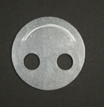
This instalment continued the work on the circles and circular arcs, to produce the very cheesy workpiece.
MEW Issue 212 : February 2014
Programs to cut the circles and the arc
If you can’t be bothered to type your own set of instructions to cut the circles and the arc for the shape shown in the magazine instalment, my versions can be downloaded using the links below.
Both programs use the physical setup shown in the magazine instalment, and take the Work Origin to be at the front left corner of the workpiece.
Both assume an end cutting 2mm diameter cutter (2 or 3 flutes).
I ran the cutter at 4000rpm, which is the top speed of my main spindle, and it’s way too slow for an optimum cutting speed, so the feed rate and depth of cut are much reduced, to save the cutter. You should note that the comments made in the articles about tool shape are very important, and the best performance comes from a specially designed cutter which has polished flutes and high cutting angles. That’s also true for lathe turning tools used for machining aluminium. Lubrication is important, and you really need to avoid heating the work. Aluminium has a high coefficient of friction, so machining will generate heat quickly. Full flood lubrication might be a good idea, but its very very messy (and marks on my wall and floor suggest it is more messy on a mill than a lathe). The wax-based lubricants like lip salve (as suggested by Mark Noel in MEW 210) or car wax can be applied locally, and show considerable promise, if you are willing to apply them throughout the cut.
I used lip slave as a lubricant, to avoid the smell of white spirit.
I did think this was an improvement, but it does make the chips stick in the grooves, so it still requires constant attention. Refill the groove as the cutter passes, and clean the cutter thoroughly between programs.
Use a decent machining grade of aluminium if you can (although it is likely you will be using thin sheet, so there may not be much of a choice available). I used a piece of sheet, grade 1050A - H14 which is far from ideal. In fact its machining characteristics are rated as “poor” on the manufacturer’s data sheet. I didn’t have much choice, though. That’s the problem with aluminium; you really need to know what grade you are dealing with. For circular section bar, grades 2011 and 6262 T9 are free machining grades which offer “excellent” or “very good” machining characteristics,
and for larger blocks or rectangular section flat bar grade 6082 has “very good” machining characteristics.
The first program cuts the inner holes and the arc.
The second program cuts the outer circle.
Download the first program HERE
Download the second program HERE
Program to engrave the legend
You will have discovered, by now, that I like to add a flourish. If you have made a decent piece of equipment or a finely finished accessory, it’s always worth just adding a touch of individuality, or something which makes it look like a professionally produced item.
In this case, its a legend.
Download the program HERE
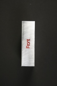
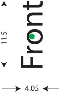
The program engraves the word “Front”.
It’s hardly an innovative design, but it does add that finishing touch, and its practical too.
The program assumes the machine vice will be orientated in the same way as shown in figs 76, 77 and 79 on page 10 of MEW 212, and that the workpiece will be standing on its end with the face to be engraved upright. The lettering will be produced “sideways” as shown in the photo on the left. The engraving is centred within a rectangle approximately 4.05mm wide and 11.5mm back to front, as shown below, and the origin is at the centre of the legend as shown by the green dot.
Getting the lettering
I got my lettering by creating the text as single line characters using the Quick Engrave facility within Cut2D. These are single line, or ‘stick’ figures, and there are other ways of getting them. Cut2D is an easy way to create text and output a finished program, as we will see in a later instalment of the magazine series.
It’s not my intention to twist your arm, but I would suggest you download the trial version of Cut2D if you are at all interested in that kind of CAM program. It is fully functional apart from the fact that it won’t save or output your own file.
There’s a discussion to be had about the pros and cons of CAM programs, but I do believe they have their place in the scheme of things, and an important place too. More later.
You will need an engraving cutter of 30 degrees total included angle (15 degrees half angle) and 0.2mm tip width. Run it as fast as you can. The program sets the spindle speed to 4000rpm, and sets the feed rate appropriately, but be aware that the proper speed for this kind of cutter is over 20 000rpm, with 30 000rpm being a good practical speed if you have a spindle which will stand up to that kind of speed. If you can achieve that speed, increase the feed rate considerably.
Set the Z height to zero at the top surface of the work. Do that using the “roller” method of raising the cutter height until a roller of known diameter can just pass underneath, between the cutter and the work. For safety, pass the roller through the gap from the front of the cutter because the tips of engraving cutters are fragile.
Lubricate the cutter during the cut, even though the faces of engraving cutters are highly polished.
I just love the contrast between the matt red and the aluminium. I could sit in the workshop and admire this kind of fixture for ages, over a cup of tea. It beats train spotting in the rain, that’s for sure.
Download the article here