CNC in the Workshop

Cutting speeds and feed rates

My mill, for example, has a continuously variable speed range between 190 and 4000rpm. If I am cutting CZ121 brass, which has a nominal cutting speed of 100M/min, the maximum diameter of cutter I can use at the theoretically correct speed will be
(100 x 1000)/(3 x 4000) = 8.3mm or a little over 8mm
Any cutter below 8mm diameter will not be turning fast enough to reach the correct cutting speed. In fact, if the cutter is carbide, the spindle speed should be around 1/3 higher, meaning the minimum cutter diameter should be around 11mm.
That’s a problem, especially because I use lots of cutters of 2 and 3mm and the odd one smaller than that.
A minimum speed of 190rpm cutting cast iron (20M/min) means I should use a cutter with a maximum diameter of 35mm. Again, that’s a bit of a pain because my favourite 3-tip facing cutter is 40mm diameter, and I have another cutter larger than that.
Spindle speed is not a factor that can be varied in the same way as feed rate, so we can’t decide to reduce the cutting speed just because the spindle is not capable of reaching the required speed.
So what do we do?
There are basically two approaches.
The first is to make the spindle turn faster. It’s probably not a good idea to run your existing spindle much faster, because the bearings will not be rated for faster speeds (and if they were, the manufacturer would surely have increased the spindle speed and charged you more for the mill). You could always change the bearings and the drive pulleys to up the speed. Or you could add a second spindle to one side of the original, mounted pn the same head. Not so difficult or as daft as it might seem, and not without some merit either. We may return to that. Let’s just note that we should be aiming for up to 30000 (yes, 30 thousand) rpm or more. That’s the speed of a router-like spindle, so it would not be hard to achieve. In fact, there are lots of gantry mills out there, and there is lots of accumulated experience of spindles able to turn at those sorts of speeds.
The second approach is to accept that we cannot achieve anything like a fast enough spindle speed, and make do with the maximum available speed. The downside is that we will need to take care with feed rate, and we may have to accept a compromised surface finish.
Once the spindle speed has been set, we can then go on to calculate the feed rate.
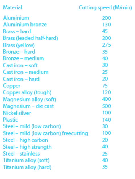
For your convenience, here are some “average” values of cutting speeds. The reality is that for each material there is a range of cutting speeds which will give good results, so feel free to increase or decrease the speeds given, to give optimum results on your own mill. The main determining factor is the exact composition of the material, and, in particular, the hardness. Aluminium, for example, comes in several different grades, all in common use. The best free machining grades can be cut successfully at around 3 times the speed of the grades with low machinability. The same is true of other materials.
Cutting Speeds
If there is a single truth, it is that whether you have a large mill or a small micro machine, whether you use large cutters or little tiny things, cutting speed (rpm of the spindle) depends only on the material being cut, the diameter of the cutter, and the material from which the tool is made. That means the cutting speed will be the same on all mills, for the same material and cutter. So you should try to achieve the optimum cutting speed no matter the make, model or size of your mill. If you like, the cutting speed is about what happens where the cutting edge meets the material, and that’s about the physics and mechanics of material and tool.
Very small diameter cutters are a problem because they inevitably require high spindle speeds. Very large cutters are less of a problem, but they will require that a low speed is available.
Whether you are using a spindle which has a set of fixed speeds (like a belt-driven spindle) or a spindle which has a continuously variable speed range, there will be maximum and minimum speeds available to you.
Strictly speaking, this will mean there is a minimum diameter of tool your spindle can drive, and a maximum diameter too.
The formula for spindle speed can be re-arranged to calculate cutter diameter, as follows-


Feed rates on small mills
The harsh truth is that most small mills are built to a price and they cannot achieve anything like industrial feed rates.
Reasons for this include lack of rigidity due to compromises in design. We are, as a consumer group, a right bunch of skinflints, and unwilling to pay high prices for what looks like an item that doesn’t cost much to make. You do get what you pay for, in this field, or rather, you don’t get what you are unwilling to pay for. The much more expensive industrial machines are just that: much more expensive, and designed for industrial duty, where feed rates are important. High feed rates mean high throughput and that’s a very much more important factor for industrial users than for the home user. But we can’t just say that becasue we don’t actually need a machine that can achieve high feed rates. High feed rates are a by product of rigidity, and rigidity is important for accuracy of cut and quality of finish.
When a manufacturer targets the home workshop skinflints, almost the only way the cost of the machine can be reduced is to lighten construction (the less metal, the lower the cost of the raw materials).
Then there is the material itself. It looks the same as what’s used in an industrial machine, but it isn’t. Your machine might be cast iron, but the industrial machine will be made of Meehanite (a trade name of The Meehanite Metal Corp) and will be stronger, of more consistent quality and, crucially, will be able to absorb vibration more effectively. There is a world of difference in the performance, and a significant difference in cost, of course.
Then there are the bearings. A pair of bearings for a mill spindle might cost £20 or they might cost considerably more than your whole mill. When I die, I’d like the undertaker to roll my coffin on a set of Gamet Super Precision bearings, as fitted to the finest machine tools in this world. I’m saving up. Try pricing a set. Guaranteed to high speeds, and made to extremely high tolerances, these are the business, and they not only allow the construction of high speed spindles, those spindles are silky smooth, with absolutely minimal play, so you get no interference with the surface finish either.
One thing you can deal with is the fit of the slides on your mill. Hand scrape or grind them in using oilstone dust or similar. Takes ages, but does improve the fit. Sloppy slides allow lots of movement under cutting pressure, and can substantially compromise finish as well as accuracy.
So, although we can calculate industrial strength feed rates, we must take account of the limitations of our machines. I would recommend viewing with suspicion any feed rate that is over 100 to 120mm/min in steel. Yes, I have used 300mm/min on occasion, but not without closing my eyes and squatting down below the level of the cutter. And not for a finishing cut.
This varies by material, though, and I have used 600mm/min on a free-machining aluminium alloy. The metal almost flowed at that speed, and the finish was wonderful to behold. You would never get away with that on a typical bit of aluminium from the scrap pile, though. You need to know the grade of material you are cutting, because that significantly affects the machining characteristics, the spindle speed and the feed rates required to achieve a good finish.
Keep notes
Personally, I think it is a good idea to keep notes on materials, spindle speeds and feed rates you have used, and the results you have achieved. Gradually, you will build up a useful body of data to guide you in selecting speeds and feeds that work for a range of materials on your mill. Sounds a bit boring and unnecessary, I know.