CNC Milling in the Workshop

Chapter 7

Chapter 7 is about:
-
 creating and using subroutines;
 -
creating and using loops;
-
taking decisions (LinuxCNC only);
-
incorporating G code created by a CAM program into a subroutine.
This web page supplements the content of the chapter. It does not repeat content from that chapter, because it assumes you have the book, and have read the chapter.
Subroutines, loops and decisions
Project 7.1
A suitable subroutine could be created using fixed co-ordinates and sizes for the circles, like this:
Assume the cutter is positioned 1mm above the material, directly above the vertical axis of the hole.
Assume the cutter is 6mm diameter, and capable of cutting at least 19mm deep (giving 1mm clearance when breaking through the bottom of the workpiece).
O100 sub (for Mach3, use O100)
G92 X0 Y0
G0 Z1
G0 X0 Y0
G1 X-5
G1 Z0
G2 X-5 Y0 I5 J0 Z-3
G2 X-5 Y0 I5 J0 Z-6
G2 X-5 Y0 I5 J0 Z-8
G2 X-5 Y0 I5 J0
G0 X-1.1 Y0
G2 X-1.1 Y0 I1.1 J0 Z-10
G2 X-1.1 Y0 I1.1 J0 Z-12
G2 X-1.1 Y0 I1.1 J0 Z-14
G2 X-1.1 Y0 I1.1 J0 Z-16
G2 X-1.1 Y0 I1.1 J0 Z-19
G0 X0 Y0
G0 Z1
G92.1
O100 endsub (for Mach3, use M99)
Project 7.2
The suggestion on page 87 (under Speeds and Feeds) that you use a 6mm end mill only applies if you have chosen to machine slots of 6mm or wider.
For the example below, I have chosen to go with the drawing (fig 7-17) and cut slots 4mm wide. The best cutter size to use is a little smaller than 4mm, but as large as possible under that size because, generally speaking, the larger the diameter of the cutter, the more rigid it will be.
exceptions to that are where the flutes are very deep, as on some of the cutters designed for cutting aluminium, or the material is brittle, such as a carbide rather than a HSS cutter.
A subroutine might assume the cutter was located on the CP where it had just reached the left bottom corner of the slot, as seen in the plan view in fig 7-17, but an alternative approach might be to assume the periphery of the tool rack had already been cut, and the cutter is positioned on the centre line of the slot, a fixed distance from the front edge of the rack (say 1mm) and at a Z height of 1mm above the top surface of the material.
Using fixed co-ordinates,
slot width 4mm
cutter diameter 3mm
the path might then be:
G92 X0 Y0
G0 X-0.5 (i.e. -2 is half the width of the slot, to the left, and +1.5 is half the width of the cutter)
G1 Z-2 (to take the tip of the cutter just beyond the bottom of the material)
G1 Y15.5 (i.e. 1 clearance + half the cutter diameter + depth of slot)
G2 X0.5 Y15.5 I0.5 J0
G1 Y-2.5 (i.e. 1 is clearance and 1.5 is half the diameter of the cutter)
G0 X0 Y0
G92.1
An alternative approach is to use variables (if you have read the rest of the chapter):
#100 = slot width
#101 = slot depth measured to the centre point of the circle defining the semi-circular end of the slot as shown by the dimension 13 in fig 7-17
#102 = diameter of the cutter
#103 = distance of the outside of the cutter from the edge of the tool rack
If G92 temporarily defines the current position as X0 Y0
move to position the left edge of the cutter in line with the left edge of the slot, at X[[-1*[#100/2]]+[#102/2]] Y[#103 + [#102/2]]
(and note the use of [ and ] to enclose each calculation)
cut to the beginning of the semi-circle
G1 Y [#103 + #101]
G2 X [[#100/2]+[-1*[#102/2]] Y [#103 + #101] I[-1* [[#100/2]+[-1*[#102/2]]] J0
cut clear of the end of the slot
G1 Y [[#102/2] + #103]
move back to the temporary origin
G0 X0 Y0
revert to former co-ordinate system
G92.1
Project 7.3
Use a 6mm diameter end mill.
Use a safe Z of 1mm above the top surface of the work.
Position the CP directly above the centre of the circle, at Z1 before calling any subroutine,
Subroutine to cut the 14mm diameter circle:
G92 X0 X0 Z1
G0 X-4 Y0 Z0
G2 X-4 Y0 I4 J0 Z-0.5
G2 X-4 Y0 I4 J0 Z-1
G2 X-4 Y0 I4 J0 Z-1.6
G2 X-4 Y0 I4 J0 Z-1.6
G0 X0 Y0 Z1
G92.1
Subroutine to cut the 10mm diameter circle differs only in the X position (which affects the I offset too):
G92 X0 X0 Z1
G0 X-2 Y0 Z0
G2 X-2 Y0 I2 J0 Z-0.5
G2 X-2 Y0 I2 J0 Z-1
G2 X-2 Y0 I2 J0 Z-1.6
G2 X-2 Y0 I2 J0 Z-1.6
G0 X0 Y0 Z1
G92.1
Subroutine to cut the 20mm diameter circle also differs only in the X position and the I offset:
G92 X0 X0 Z1
G0 X-7 Y0 Z0
G2 X-7 Y0 I7 J0 Z-0.5
G2 X-7 Y0 I7 J0 Z-1
G2 X-7 Y0 I7 J0 Z-1.6
G2 X-7 Y0 I7 J0 Z-1.6
G0 X0 Y0 Z1
G92.1
A general purpose subroutine using variables to cut any diameter of circle in material 1.5mm thick, using any diameter of cutter:
#120 = diameter of hole
#121 = diameter of cutter
#122 = [#120/2] (half the diameter of the hole)
#123 = [#121/2] (half the diameter of the cutter)
#124 =[-1 * [#122-#123]] (X distance to move CP to position the circumference of the cutter on the circumference of the circle)
G92 X0 Y0 Z1
G0 X#124 Y0 Z0
G2 X#124Y0 I[0-#124] J0 Z-0.5
G2 X#124Y0 I[0-#124] J0 Z-1
G2 X#124Y0 I[0-#124] J0 Z-1.6
G2 X#124Y0 I[0-#124] J0 Z-1.6
G0 X0 Y0 Z1
G92.1
Note that the subroutine above does not check for daft situations such as the cutter diameter being larger than the diameter of the hole.
A Library of Subroutines
Its not hard to imagine a set of subroutines which could be loaded into any program (or perhaps every program). That would mean we could start writing a program by loading a skeleton program which would consist of: (and you can refer to fig 5-1, page 52 at this point)
-
 an empty information block with brackets ready to accept comments.
Since a lot of information in this section is always provided, like the name, date of creation, position of the Work Origin, material, tool, and so on, labels for those could be pre-written. -
The initialisation block is the same every time, so that could be included.
-
The Operation block (i.e. the main program) could be indicated by a feed rate and a speed command, a move to safe Z and a move to X0 Y0
-
The end statement could be included.
-
A set of useful subroutines could be included too, to be called if and when required. The position of those would be different for Mach3 and LinuxCNC, but that is a minor detail.
The principle is a sound one, and can save a lot of time.
Typographical error on page 80
In the Mach3 box in the bottom corner of page 80, the fifth (and last) command should be:
G0 X26.5 Y30 (and not Y90)
For the program shown in the Mach3 box at the bottom of page 80 and the top of page 81 the idea is that the program takes the CP in turn to
X26.5 Y30 and cuts a hole there, then takes it to
X26.5 Y60 and cuts a hole there, then takes it to
X26.5 Y90 and cuts a hole there.
With the command as printed on page 80, the program will cut one hole twice, and miss one hole altogether, which is just daft.
This is a good reason to check the Toolpath window carefully to make sure what’s shown there makes sense.
I did; but something seems to have happened after that....
Typographical error on page 81
The code for the subroutine to machine the socket uses G1 commands throughout, and most of those should be G2 commands.
If you type the commands as shown at the bottom of the first column and the first half of the middle column, you will get error messages complaining about the syntax of the G1 commands. Quite right too.
Here’s what the code for the subroutine should be:
(Instructions for machining a single socket)
(Machine the large hole first)
(It is currently centred at X0 Y0)
G0 X11 Y0 Z0
G2 X11 Y0 Z-1 I-11 J0
G2 X11 Y0 Z-2 I-11 J0
G2 X11 Y0 Z-3 I-11 J0
G2 X11 Y0 Z-4 I-11 J0
G0 Z1
G0 X0 Y0
(Machine the two 2.5mm tapping size holes)
G0 X-12.25 Y-9.5 Z0
G2 X-12.25 Y-9.5 Z-1 I0.25 J0
G2 X-12.25 Y-9.5 Z-2 I0.25 J0
G2 X-12.25 Y-9.5 Z-3 I0.25 J0
G2 X-12.25 Y-9.5 Z-4 I0.25 J0
G0 Z1
G0 X12.25 Y9.5 Z0
G2 X12.25 Y9.5 Z-1 I-0.25 J0
G2 X12.25 Y9.5 Z-2 I-0.25 J0
G2 X12.25 Y9.5 Z-3 I-0.25 J0
G2 X12.25 Y9.5 Z-4 I-0.25 J0
G0 Z1
G0 X0 Y0
Each of those G2 commands takes the CP right round in a circle.
That’s a handy way of machining a circle.
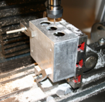
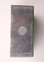
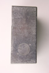
The die cast boxes cut beautifully, but do take note of the need to level the surface being cut, especially when using a small diameter (and therefore fragile) cutter. The taper is a right nuisance.
Tilting table
Note that I cannot recommend or endorse the tilting table seen in fig 7-7. The design is good, and there is no doubt this kind of table is a really handy accessory, for two reasons:
the first is that it tilts (obvious, really....)
the second is that if the top is set parallel to the base it makes a really useful sub-table which lifts the work above the main table - very handy for small cutters when the head struggles t get down low enough to reach thin work on the main table - and it has T slots for clamping work securely.
All great; except that this particular model was so shoddily made it went straight back to the vendor. Top surface was not level; T slots were squint; T slots were not of uniform width across the table; hinge pin end stop looked as though a child had made it with a blunt chisel and a very large hammer. If I say I was disappointed, that would be a bit of an understatement. Disappointed that it was faulty, but also disappointed that someone should sell an item like this which was clearly deficient even to the casual onlooker.
Give the vendor his due; I received a prompt no-quibble refund.