CNC Milling in the Workshop

Chapter 6

Chapter 6 is about:
-
 using G code commands to create arcs and circles;
 -
using CAM software to create a program containing arcs, circles and polylines.
This web page supplements the content of the chapter. It does not repeat content from that chapter, because it assumes you have the book, and have read the chapter.
Arcs, Circles and Polylines
Project 6.2 : Yacht Servo Arm
The challenge with this Project is in drawing the shape. The techniques outlined in this chapter work fine, but in case you are impatient to get going, or want proof this shape can be drawn,
the Cut2D file can be downloaded here,
and the DXF file of the shape, drawn in AutoCAD or Illustrator and saved as a DXF, can be downloaded here.
Open the Cut2D file in Cut2D version 1.5 and practice defining the toolpath. That file will also open in VCarve Pro 6.5 or above. It may well open in earlier versions, but I have not tested that.
Create a new (blank) file in Cut2D, then import the DXF file.
Alternatively, from within Cut2D, try Opening an existing file, but choose the DXF file as though it was an existing Cut2D file. It should open without difficulty. The advantage of doing that is that the material size will be set to the maximum dimensions of the drawn object. Cut2D should automatically open the Job Setup dialogue box to allow you to see the sizes set, and to alter the Z thickness. If it doesn’t do that, or you decide to change the thickness later, use the Edit > Job Size and Thickness menu.
Project 6.1 : Steady Bar and Foot
This is an interesting little object, and we can tackle its production in two fundamentally different ways.
The first approach is to create a hand-written program which recognises that, looking at the plan view of fig 6-7 on page 71, we do not know the co-ordinates of the two points where the left hand arc (radius 10.2mm) meets the horizontal lines forming the sides of the foot.
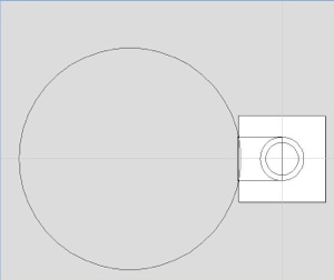
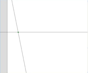
But we can simplify the shape by thinking of it as a rounded rectangle and a larger circle (diagram 1 on this web page).
Start by taking the Work Origin to be 0, 0 at the centre of the steady bar (the green dot in diagram 1).
Use the select tool to select the 2mm radius circle then shift-select to select the rectangle as well.
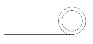
Choose the Weld selected Vectors tool. That makes the rectangle and the circle one closed shape. Note that it deletes lines which lie within the boundaries of either shape, leaving just the outline of the composite shape. See diagram 4.
The next task is to join the small overlapping arc of the large circle with the rectangular end of the composite shape.
We can’t use the Weld tool to join these shapes, because it will omit the small part of the curve we need to retain, inside the rectangle, leaving the rest of the large circle, which we don’t want.
In other words: the Weld tool deletes shapes inside the largest outer boundary it can make when it joins the shapes together. We want to join two inner shapes and get rid of an outer shape, so that’s not the tool for this job.
Instead, we will use the node editing tool to cut the large circle where it crosses the rectangle, and delete the larger portion that we don’t need. Then we will cut the rectangle where it meets the ends of that small arc, and delete the bit to the left that we don’t need. Then we will join the arc to what’s left of the right hand shape.
Use the Select tool to select the large circle. Choose the Node editing tool and place the pointer over one of the spots where the large circle crosses the rectangle. Right click and choose Cut Vector.
Repeat for the other point.
Using the Select tool, select the part of the circle on the left; the part that is not required for the final shape. Delete it.
Use the Select tool to select the composite shape you created earlier (with the rectangular end on the left). Choose the Node editing tool and place the pointer over one of the spots where the short arc should meet the rectangle. Right click and choose Cut Vector. Repeat for the other point.
Using the Select tool, select the rectangular end you now don’t need, and delete it.
Choose the tool to Join/Close Vectors with a Straight Line.
Drag a selection rectangle around the top end of the arc and the left end of the top horizontal line of what was the rectangle.
Repeat for the lower end of the arc.
If you need to extend the size of the workpiece to ensure the final piece fits within its boundaries, do that now, using Edit> Job Size and Position
Job done.
You can now select the outline of the foot, and have Cut2D calculate a profile toolpath. I used a 6mm end mill with a pass depth of 1mm, speed of 3000rpm and feed rate of 100mm/min.
When defining the toolpath I set the total depth of cut to 7mm, an Outside path, with Conventional direction.
That cuts a foot 7mm deep.
You can now select the smaller circle, representing the steady bar, and have Cut2D calculate a toolpath for that, using the same end mill, pass depth, feed and direction, with a total depth of cut set at 5mm.
Previewing all toolpaths should result in a realistic representation of the foot. Remember you can tilt the preview to get a better view of the finished object.
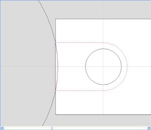
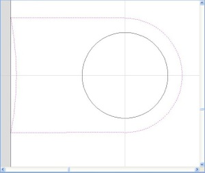
Machine around the periphery of the foot but imagine it extends well to the left as shown in diagram 2.
Then machine a large circle, radius 10.2mm and centre point at -14, 0.
There will be a lot of cutting in the air, when the large circle is machined, but that’s not a problem; it just adds a little time.
To complete the workpiece, machine a circle 5 deep (in stages, of course).
The code for a completed program can be downloaded
for Mach3, here,
for LinuxCNC, here.
Note my comments at the end of the project notes (below).
A second approach is to draw the object in Cut2D and make that software output the program code.
The challenge is in drawing the object, because until you become familiar with the tools and methods in Cut2D, this kind of object can be a bit of a puzzle. Then again, that’s why this project is here.
Start Cut2D and choose to create a new file.
make the material size 8 x 8mm, 7mm thick, with the origin in the centre. The material size is just a guess, at this stage. We can deal with that later.
Looking at Fig 6-7 on page 71, in plan view:
Draw a circle of 3mm diameter, centred on 0, 0
Draw a second circle radius 2, centred on 0, 0
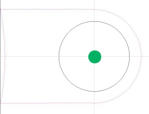
Draw a rectangle with the top and bottom lines tangent to (just touching) the larger circle, the right hand end on the diameter of that circle, and the left hand end a couple of millimetres off the left end of the material (diagram 3). This is best done by selecting the Rectangle tool, and using the direct entry dialog box to define the centre as -5, 0 with a height of 4 and a width of 10. The height should be the same as the diameter of the circle of radius 2 (diameter 4) and the length a nominal 10mm, extending to the left, making the centre at -5, 0. Or you can just do the whole thing by eye.
If you do draw the rectangle by eye, and you need to adjust the positions of the top and bottom lines, do that now, using the Node Editing tool (or just delete the rectangle and draw another one). Zoom in, if you are editing the drawing; it makes life so much easier.
Draw a circle with radius 10.2mm, centre -14, 0
Diagram 1
Diagram 2
Diagram 3
Diagram 4
Diagram 5
Diagram 6
An important thought
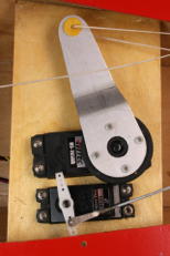
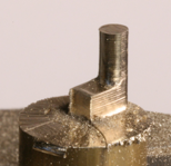
The two methods of devising programs are fine, especially as they illustrate the techniques from chapter 6. But f you examine the photo of the finished object at the top of the page, the finish is - what shall we say - a bit on the rough side. The programs work, but the outcome illustrates that in real life we do need to be a bit more cunning.
I had a substantial number of these little steadies to make, so having to polish up the machined pieces was not something I wanted to spend a week or so doing. Besides; there’s pride at stake.
There are three factors affecting the finish.
-
(1)I used a 14mm diameter endmill to try to get the peripheral speed of the cutter closer to the ideal. That cutter had previously been used on steel, and although sharp enough to draw blood from my finger, it was not sharp enough for machining brass. The old wife’s tale about not using a cutter on steel if you intend to use it on brass is true.
The geometry is wrong too, because cutting angles for steel are very different from those for brass, but I can’t do much about that at present. -
(2)You may be able to see the cutting marks indicating the different depths of cut. There are two reasons for that. First, I need to check the alignment of my spindle. Secondly, we can eliminate those marks by taking a final fine cut at full depth over each of the paths we used. That means, though, that we need to cut the paths a few tenths of a millimetre oversize until the final pass. I leave it to you to work out the changes that requires to the co-ordinates used in the example programs. Take one final cut at the final set of co-ordinates at the end of the passes for each path. high speed and fine feed is the order of the day, so reduce the feed rate a little for those final passes.
-
(3)Feeding directly into the work is not the best technique. It is better to either (a) approach the work from a point at which cutting is not important, or (b) ramp down to the cutting depth as the cut begins. That does mean subsequently reversing to the beginning of the cut once cutting depth has been reached, and starting the pass from there, or starting the cut at a position which allows the cutter to ramp down and reach cutting depth before it reaches the start of the cut.
There is an example of (a) at the start of the cut for the foot, where the first point has an X co-ordinate of -14, yet the corner of the path for the rectangle is at X-13. The first movement down to depth for the first cut takes place in the air, before the cut advances along the side of the foot.
Most CAM software has an option to allow ramping into a cut. Cut2D certainly does, and I recommend you investigate and use it.
Spiralling into the work, and turning corners using arcs are both mentioned on page 69 of the book, and they are there because they make a difference.