CNC Milling in the Workshop

Chapter 5

Chapter 5 is about:
-
 manually creating, editing, saving and running a CNC program;
 -
creating a CNC program by using CAM software;
-
manually editing a CNC program initially created by CAM software.
This web page supplements the content of the chapter. It does not repeat content from that chapter, because it assumes you have the book, and have read the chapter.
Linear programming
Here’s one I wrote earlier
One of the more interesting aspects of a decent program structure is that you can easily edit it to suit another purpose.
So if I gave you a program which had a nice clean, well-commented structure, not only would that be quite unlike me, but you could identify which part of the program did what, and modify it to suit yourself.
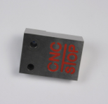
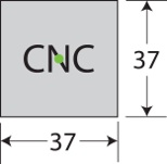
So here’s a program to mill a legend, as shown in the photo at the side. The legend is the word CNC.
It is designed to fit in the centre of a space of approximately 37mm x 37mm on a workpiece 6mm thick (although the thickness doesn’t matter in this case, because the cut is only 0.2mm deep).
Download the program to cut the logo,
for Mach3, here.
for LinuxCNC, here.
(Note: these are zip files, so you will need to unzip them once you have downloaded them.)
Load it into your CNC program, and check that the toolpath shows you the lettering - or at least the path the CP will take to create the lettering. Then look at the code (using the editor). If you prefer, you can load the whole program into a text editor.
In particular, check the comments which tell you what the various parts of the program do.
Save a copy of the program using a different name, delete
the sections which machine the letter N, then save that version of the program.
Now load that version back into your CNC program and look at the toolpath. It should only show the path for the CP to create the letters C and C.
Note carefully, though, that this new version uses the same Work Origin as the original, so if you were intending to machine this path, you would still need to set the Work Origin as shown by the green dot on the drawing at the side. Not too much of a hardship with this program, but something to be aware of if the path was more complex, larger, or the remaining part was further away from the position of the Work Origin.
Note, too, that the letters C and C do not close up to occupy the space created by removing the N. The co-ordinates of the letters are fixed in relation to the Work Origin.
If you want to see my modified versions, you can download them
for Mach3, here.
for LinuxCNC, here.
Typographical error on page 51
At the bottom of the third column, the
Alternative instructions for inches
seem to have gone awry.
Firstly, the Y values are all the same, so the holes will all be on the same horizontal line, and the last three holes will be drilled on top of the first three, which is rather silly.
Secondly, the Q values are all 3, which doesn’t make much sense. It would be better if those were the inch equivalent of 3mm, i.e. 0.125
If Q is 3, that is much more than the entire Z depth of -0.375 which doesn’t make much sense and won’t have the desired effect of creating a series of steps down and retracts to clear the chips.
Thirdly, the second line reads GO X0 Y0 so the GO should be G0 (that’s a zero instead of a capital letter O).
Here’s what the instructions should be (and note that I have spaced the individual parts of each instruction across horizontally, to make it easier to read the values, but the extra spaces do not have to be typed into Mach3):
G0 Z1
G0 X0 Y0
G83 X1 Y0.375 Z-0.375 R0.1 Q0.125
G83 X2 Y0.375 Z-0.375 R0.1 Q0.125
G83 X3 Y0.375 Z-0.375 R0.1 Q0.125
G83 X1.5 Y1 Z-0.375 R0.1 Q0.125
G83 X2.5 Y1 Z-0.375 R0.1 Q0.125
G83 X1 Y1.625 Z-0.375 R0.1 Q0.125
G83 X2 Y1.625 Z-0.375 R0.1 Q0.125
G83 X3 Y1.625 Z-0.375 R0.1 Q0.125
G80
G0 X0 Y0 Z1
M5
M30