CNC Milling in the Workshop

Chapter 3

Chapter 3 is about:
-
 two ways of making your mill move
This web page supplements the content of the chapter. It does not repeat content from that chapter, because it assumes you have the book, and have read the chapter.
Basic Movement

Keyboards
The workshop can be a hostile environment for keyboards, and mine sits on a swivelling stand attached to one corner of the cabinet on which my mill sits. It gets showered in swarf and has a short life as a result. My fault; but its a consequence of its convenient position.
I have recently replaced it with a neat sealed keyboard which claims to be liquid-proof. We’ll see; but so far, so good.
There are details of the keyboard on the page dealing with the construction of a CNC computer, here.
Pendants
One of the things I find is that I need an extension cable for my mouse and keyboard so that I can swing the keyboard stand around to allow me to reach it when I am adjusting something at the chuck. Sometimes, I work with the keyboard in one hand as I squint down at an alignment mark on the workpiece. That’s why I think a pendant would be a good idea. There are lots out there for Mach3, and a few which should work with LinuxCNC too.
More details as I try some out.
in the meantime, so that you know what I’m talking about, there are some examples here , here and here.
Pen holder
A pen or pencil is a useful tool for tracing out a planned machining path.
Page 33 of the CNC Milling book shows the simplest arrangement (fig 3-5) in which a pencil is held in the drill chuck. That works fairly well, but suffers from a couple of disadvantages, especially if you will be using this technique frequently.
First, there is no compensation for wear of the pencil point, so the trace will tend to fade over a long or complex path. Secondly, there is no resilience in the mount, so misjudging the distance to the paper will fracture the point of the pencil. The pencil needs to press on the paper to make the trace, so there is a fine judgement to be made as to the (very small) depth of “cut”.
To protect the pencil point, you can always grip it lightly in the chuck, so that it can slide a little if the pressure on the point is too high, but it won’t spring back down as wear takes place, so that’s not a complete solution.
What’s needed is a tiny bit of resilience.
That could be achieved by putting a thin sheet of foam from the craft shop under the paper, but the problem with that is that the paper then flexes and can easily be torn.
So the resilience needs to be associated with the pencil or pen.
Resilience is a two edged sword, in many ways, because too much resilience will mean the writing point tends to stay on the surface momentarily as the Z axis is moved upwards. A tiny dwell is not a huge disadvantage, but if you have a fancy holder with a long soft spring and lots of resilience, it becomes a problem because your retracts need to be vertical and quite large. Fine if you are doing a relatively simple path, but if you are doing a drawing with many paths and lots of gaps between paths, it will prolong the task.
Standard “Biro” type pens are cheap as chips, and perform reasonably well, so that’s a good place to start; and, at a few pence per pen, accidents are not expensive, which is a bonus.
Take one standard “Biro” type pen, and remove the insert, leaving you with the ball tip and the ink tube. Take a sharp scalpel and cut through the ink tube roughly 30mm from the step on the front ball holder. This is a potentially messy operation, but one way to do it is to roll the tube as you apply pressure on the scalpel, and slice through without crushing the tube. Needless to say, you will be doing this on a surface on which stains don’t matter…
Put the pen in a drill chuck or a suitable collet, and away you go. The point will stand a little pressure, and the plastic ball holder has a very tiny but useful amount of resilience, so it should survive for a while.
Set Z0 using a roller (see page 26 and fig 2-29), by setting to the roller and entering the diameter of the roller directly into the Z DRO. For my roller, that’s 25.000
Now Z0 will correspond to the pen touching the paper.
To make the pen actually write, you will need to apply just a little pressure, and Z-0.1 seems about right on my mill.
Use MDI mode to enter the feed rate command F200 and away you go.
To allow you to test this out, you can download a ready-made program for Mach3 from here, or for LinuxCNC from here.
The program contains a large number of instructions, so may not be happy in the demo version of Mach3. Within the program the feed rate is set to 200mm/min, and the program takes approximately 30 minutes to run.
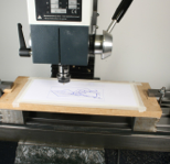
Use paper of a decent thickness and quality, and take time to flatten it carefully as you tape it down to a board. I used MDF because of its uniform thickness. I also found I had to raise the board off the bed of the mill, because with such a small projection of the pen tip from the collet holder, the Controlled Point (i.e. the ball at the end of the pen tip) couldn’t quite reach the board. The photo shows that I supported the board on two ground blocks of identical thickness. They are actually chuck jaws from a large CNC lathe, but anything of around that size will do, provided the board lies parallel to the mill table.
The drawing occupies an envelope approximately 150mm left to right (along the X axis) and 70mm back to front (along the Y axis). Set the work origin at the front left corner.
Drawing begins some way into the space.
The little wiggly bits around some of the lines are an attempt at shading. Well; I’m no Rembrandt.