CNC Milling in the Workshop

Chapter 1

Chapter 1 is about:
-
 the process of getting from a design to a finished workpiece;
 -
details of the software systems you might use;
-
some of the mechanical and electronic systems used in CNC milling machines.
This web page supplements the content of the chapter. It does not repeat content from that chapter, because it assumes you have the book, and have read the chapter.
Fundamental Concepts
Workflow is not something we talk about very often, in the home workshop, but we frequently use the concept when we tackle a job. Workflow is simply the method we use to take a piece of raw material and turn it into a finished article. It is the steps we take, and the methods we use, to do the work that’s required. For a straightforward one-off job, we may use a few simple operations, like a turning operation, some filing, and a cut with a hacksaw. But most of us know quite well that a workshop project can easily involve a considerable time in planning the best way to do a job, before actually doing it; and some jobs must be done in a specific order, otherwise we end up not being able to grip the work, or we foul a cutter or are left with an impossible machining setup. For repetition work, workflow is important to optimise the manufacturing process and allow us to do the work efficiently.
Preceding all of that is the design process, and the need to consider manufacturability as we create a design. It is surprisingly easy to design parts which cannot be manufactured easily, if at all. Many of the commercially available castings we might use in the workshop have extra bits cast into the pattern. These form chucking pieces, and although they are not required on the finished article, they are needed to allow the part to be gripped in a chuck or clamped to a mill table for the rest of the workpiece to be machined. They are the result of considering manufacturability at the design stage (or sometimes modifications as a result of bitter experience…).
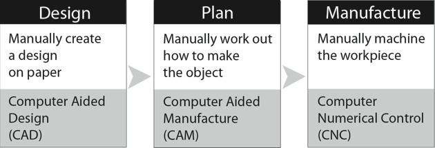
In the modern home workshop, design can be carried out at least partly on the computer, using Computer Aided Design (CAD) software which will allow the part to be drawn and the design to be tested and finalised before cutting any metal. Information from the CAD program can then be used to enable Computer-aided Manufacturing (CAM) which makes use of CNC machines to produce finished workpieces. The key to this is software for CAD, CAM and CNC, along with a compatible CNC machine.
We do not always need to use all of this software in the home workshop, but we will need to carry out all of those stages. For some tasks, it is quicker and easier to do some of the stages manually, but in other cases it is impossible to do without all the elements of the full system.
Here’s a simple piece of work based on simple shapes, which can be designed on the back of an envelope and planned on a postcard, then cut on a CNC mill.
In practice, that’s exactly what happened. I had some turned vases which needed simple bases to sit on, to complete the effect I wanted to achieve.

Grabbing a sheet of material, I drew appropriate circles around the existing vases, wrote a few lines of instructions straight into the CNC program which controls my mill, and cut the shapes using one cutter to produce a concave edge around the shapes, and an end mill to cut the vertical sides, releasing the shapes from the sheet. The advantages of using CNC for this job were that the final cut gave me a finished object which only required the edges to be burnished by hand, but the program cut three bases of the same size, then, with just a few extra instructions cut a single larger base, and all without moving the workpiece.
Even using CNC for just one of these shapes would have been quicker than cutting it by hand, because the shape was so accurately cut. Yes; the job could have been done using a rotary table in a manual mill. It would not have been any easier, though; and it would have taken much more time to set up the blanks before machining each plinth.
Here’s an engraving which could be drawn by hand, assuming a high degree of artistic ability and a lot of time and concentration, but could not be planned without the aid of sophisticated software.

Once planning has been completed, cutting the design using a CNC machine is quite straightforward. Lacking years of practice in hand engraving, I can’t think of a way of doing this manually, without an engraving machine. Even then, the job would have required some means of using the sketch to guide the cutter, and that introduces a significant element of variability. In this case, CNC is much quicker and much more reliable.

Computer Control
From early beginnings in the 1950s, CNC systems have evolved through proprietary industrial systems to the present day when users in the home workshop can choose from a range of ready-packaged systems or general-purpose control software.
Early industrial automation systems were mechanical, and were based on cams which moved parts of a machine in specific ways, and the cam-auto lathe was common in factories.
The next step was Numerical Control (NC), in which servo motors controlled by electronics moved machine slides to positions specified by holes punched in paper tape.
Finally, as computer systems became more widely available, Computer Numerical Control (CNC) allowed more flexible control of slide movement by cutting the time required to create punched paper tape and, latterly, adding many user-friendly features to the process of programming and control.
A lot of the early development work for NC and CNC systems was done by universities and military research and development teams, and there were early moves to standardize the way the systems worked, leading to the RS274 standard for commands to control these machines. This led on to the Next Generation Controller (NGC) project by the American National Institute for Standards and Technology (NIST) which resulted in a set of standards for the RS274/NGC control language interpreter and produced a core set of software for controlling the movements of the axes of a machine tool. That core software lies at the heart of much of the CNC control software currently in use industrially, as well as in the home workshop. Any specially written custom control systems should conform to the RS274/NGC standards so that all CNC systems should respond in a similar way to a set of standard commands. There is room, though, for systems to add facilities or to interpret unassigned commands in a specific way, and commercial systems inevitably differ in detail as manufacturers attempt to sell systems with added bells and whistles.
In the home workshop, the two main pieces of general purpose CNC software are Mach3 and LinuxCNC (formerly known as EMC or EMC2). These both respond to the core set of RS274/NGC commands, but both provide a user-friendly interface on screen, to make the system easy for ordinary humans to use. Both systems have developed over the years, and have gradually taken different routes, although they both still respond in a similar way to the same core RS274/NGC commands. Other software systems are available, and they do essentially the same job, so it is relatively easy to change from one to another.
Mach3 was developed by ArtSoft and is a commercial product available as a limited demo version or a fully licensed version.
LinuxCNC is Open Source software available free under a GPL licence.
Mach3 runs on a PC under the Windows operating system and uses easily accessible menus to allow the software to be configured in various ways, to suit the machine it is controlling, or to enable common tasks to be carried out quite easily.
LinuxCNC runs on a PC under the Linux operating system (and UBUNTU 10.4 in particular) and has evolved into a highly capable programming system. It does, though, depend on a familiarity with Linux, and although arguably more flexible than Mach3 in some ways, that flexibility can only be fully achieved through a greater knowledge of software and computing skills.
Component parts of a CNC system
In essence, a CNC system comprises a machine tool with arrangements to move the position of the tool in relation to the work; and a computer system with software to control those movements. The user provides a set of commands which the computer system interprets to produce control signals for motors attached to the machine tool, to move the work or a tool or both.
We will not get involved in Computer Science, but there are a few key concepts which should help clarify some aspects of Mach3, so we will dip our toes in, very gently, to the shallow end of what goes on under the bonnet of a computer used for CNC.
Here’s a simplified view of the component parts of the software in a computer system, and they have direct relevance both to CNC systems as a whole, and to Mach3, LinuxCNC and similar software.
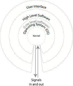
n broad and simplistic terms, the user uses “high level” software packages such as word processors or games or CNC programs. Those programs use the Operating System (OS) to run within the computer system.
The heart of the operating system is the kernel which controls all the hardware resources in the computer – the memory, the CPU, mouse, keyboard, and peripheral devices.
Every computer motherboard has a Basic Input/Output System (BIOS) which is contained in a chip which runs when the computer is switched on. A BIOS is specific to one make and model of motherboard, and its first task is to load the kernel into the computer. Most kernels are designed to work as part of a specific Operating System (OS) such as a particular version of Windows or Mac OS or Linux, and are designed to provide “abstraction” between the OS and the hardware in the computer system, relieving the rest of the OS, and all the other software in the computer system, from having to deal with the excruciating detail required to control the hardware. Instead, the rest of the OS simply passes control requests to the kernel. The kernel uses device drivers (little bits of software specific to particular hardware devices) to control individual pieces of hardware in the system. You may have come across some of these device drivers, especially if you use the Windows OS. Each time you add a new piece of hardware to a computer system, the OS requires a device driver for that hardware.
As far as the human user is concerned, software packages such as Mach3 are “high-level” programs which are easy for the human operator to use, but they need to communicate with the kernel, because it is that kernel which will enable the package to send signals out of the computer to control a machine tool. High level programs hide the detail of the manipulation of the CPU, memory and peripherals from the user by letting the OS and the kernel handle those processes. To set Mach3 up to control a specific machine we will need to enter appropriate settings within Mach3 to allow that high level package to communicate effectively with the kernel, to make sure the correct signals are sent out to the peripheral motors or received from the sensors on the machine. On a machine supplied as a complete package along with software, those settings should have been entered as the machine was commissioned, before delivery. They can be altered later, though, if need be. On a home-constructed machine, it is up to the user to enter appropriate settings. Fortunately, it is not difficult.
To complete the picture, a real-time OS is one which is designed to send or receive control signals or sensor inputs fast enough to control a machine tool so that the required movements occur at the appropriate times. It wouldn’t be much use if a tool arrived in position after the workpiece had moved to some other position. Some operating systems are designed to operate in real-time, while most others do their best, succeeding to varying degrees. This is a significant consideration, and, in the real world, it requires some awareness of the problem and some reasonable compromises to achieve a performance close enough to real-time to control a CNC system with sufficient accuracy to allow it to produce accurate work. One strategy is to use an OS like Linux which can be made to operate close to real-time, another is to use a non-real-time OS like Windows but take steps to make the signal handling capabilities sufficiently close to real-time to allow CNC systems to function.
Mach3 runs under Windows but goes to considerable lengths to make the CNC control as close to real-time as possible. This involves a lot of complex techniques, most of which we can afford to ignore. Instead, we can remain blissfully ignorant as we use Mach3 as a high-level package designed to be convenient for humans to operate.
Within a CNC software package, there are some settings we can make to allow Mach3 to operate our specific CNC machine. Most of these settings need to be made just once, for a specific machine, but a few can be altered from time to time, depending on how we want the machine to behave. The main purpose of the settings is to direct the kernel to use appropriate connections to the CNC motors and sensors, so they provide a way for abstraction to take place. Once the kernel has the settings, there should be no need to change these unless the basic physical setup of the CNC machine, its motors and sensors, changes. The settings are stored in a file and each time Mach3 starts up it will load the file and use those settings.
Most of the settings we will want to change from time to time are not directly related to the kernel, but relate to higher level functions we humans can use to define the way in which the software interprets the instructions we enter, like the extent to which the CNC machine can deviate from the path we have programmed, rounding corners, allowing speed fluctuations, and other aspects of the operation.
When we run the CNC software, we enter commands to control the movement of the CNC machine. The NIST core software built into Mach3 interprets the commands and turns those into instructions which can be passed to the kernel to control the CNC machine. The software allows co-ordinated movement of the various parts of the CNC machine, and that is why the fact that Windows is not a real-time OS makes life so challenging for Mach3, under the bonnet. In fact, the key to the success of Mach3 is the very cunning timer it creates within the computer, so that signals are sent to stepper motors or servos at a consistent and nearly-real-time rate. This is far from a simple undertaking, and requires Mach3 to effectively bypass parts of the Windows OS to create a timing system largely independent of Windows.
A typical CNC mill
Most CNC mills in the home workshop are easily recognisable as vertical milling machines. It would be just as easy to control a horizontal mill, but the vertical mill tends to be more versatile, so that’s what we will deal with, at least for now.
Vertical mills are typically either benchtop mills in which the distance between cutter and work is changed by moving the head up or down, or knee mills in which the table assembly moves up and down and the head remains stationary.
For CNC it doesn’t matter. What is important is the position of the Controlled Point (CP), a specific point which defines the position of the tool in relation to the workpiece. The Controlled Point is usually a point at the end of the tool, aligned with the vertical axis of the spindle.
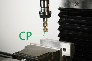
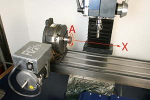
Moving the table and/or the head moves the CP relative to the workpiece. Conventionally, the movement of the CP is described using axes labelled X, Y, Z, A, B and C. The X, Y and Z axes refer to movement right and left, forward and back, up and down
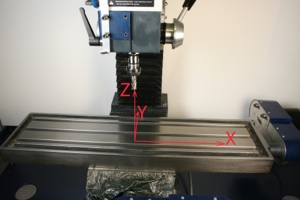
The other 3 axes, A, B and C, can be flexibly defined, depending on your machine, and each can be either a rotary or a linear axis. Where these are rotary axes, they are defined as:
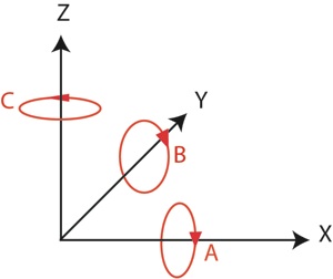
For our purposes, the A axis will normally represent rotary movement, typically of a rotary table mounted either horizontally or vertically:
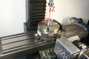
From a purely economic point of view, we are unlikely to have two rotary axes in use at any one time, so swapping a rotary table from vertical to horizontal or vice versa will be quite convenient. Because we are likely to be using that same rotary table as an axis, it can remain plugged into the same connector and be controlled by the A axis signals no matter its orientation, horizontal or vertical. We will leave B and C for the moment, because four axes are quite enough for most tasks. You should be aware that most CNC software can simultaneously control and make co-ordinated movements in up to 6 axes, because the NIST core software built into most CNC software packages provides that control.
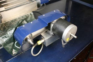
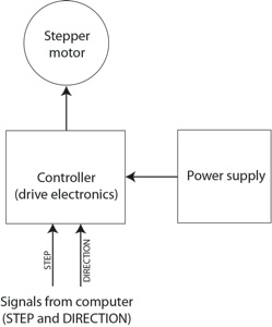
Axes are moved by a motor which can be controlled by signals from a computer or other similar device. In practice, that means a stepper motor or a servo. A stepper motor is a brushless DC (direct current) motor which is designed so that its shaft can make small rotary movements called “steps”, with a typical stepper motor being capable of 200 steps, each of 1.8 degrees, as it makes a single full rotation of the shaft. Whereas a conventional DC motor will spin as long as power is applied, then coast to a stop, a stepper motor will only appear to spin if it is rapidly moved in a series of steps. So although this is a rotary device, its rotation can be accurately and repeatably controlled. A typical movement may consist of several complete rotations and a partial rotation, all accomplished by making a series of steps. Typically, a stepper motor is controlled using two signals; a step signal to make the motor take a step, and a direction signal to control the direction of rotation. This means it is a relatively simple task to write a program to control the rotation of a stepper motor. It is the kind of programming task typically undertaken by students learning programming, and it has become a popular task for hobbyists and students using the Raspberry Pi computer, the Arduino and lots of other similar systems.
The signals from the computer need to pass through some electronics on the way to the stepper motor, to provide enough power for the motor. This is called a stepper controller and it contains the drive electronics.
Looking back to early CNC machines in the home workshop, one of the problems was that stepper motors tended to be on the small size, and used relatively unsophisticated electronic controls. Nowadays, powerful stepper motors are available at reasonable cost, and there are standard tried and tested electronic devices available to allow accurate control. Collective experience has taught us there are good solutions.
On my own mill, the stepper motors are size 34, rated at 480Ncm, meaning they have a mounting flange of a particular physical size (3.4 inches) and capable of a specific holding torque (480Ncm) although the turning torque drops off rapidly as the speed of rotation is increased. There is a trade-off in motor size and cost, and while I favour larger motors which can loaf along well within their capacity, they are more expensive, and require larger power supplies than smaller steppers.
The controllers are standard Geckodrive units (model G201). In fact three are rebranded Geckodrive units supplied under a UK manufacturer’s brand name. The fourth is a Gecko-branded unit.
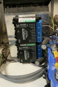
The power supply is home made. The steppers run at up to 80 volts, and the power supply can provide 78 volts at 30 amps, so it is very much more powerful than most smaller commercial units, and rather more powerful than is required. This power supply has soft-start, over-voltage protection, and current limiting, to prevent disaster and to protect the electronic motor drive units. The newest Geckodrive unit, the G203X, has considerable protection built in, so that a simpler power supply may suffice.
Many of the well-known suppliers now sell powerful stepper motors which require just a little less current, and ready-made power supplies and control units are available to match.
A servo does the same job as a stepper motor, but incorporates both a motor and an encoder which provides an error signal when the servo has not reached the commanded position. Electronics in the servo will continue to move the motor until the commanded position is reached. Although a stepper motor may receive a series of step and direction signals, there is no way of checking whether it has been able to carry out those steps or whether the motor has stalled, perhaps because a slide has jammed. Under the same circumstances, a servo motor will continue to indicate an error until it finally manages to reach the commanded position. In fact, the main issue is likely to be whether a slide has been moved to a particular position. Where there is backlash in a feedscrew, and the control software does not take this into account, any reversal in direction will result in some lost motion due to the backlash using up some of the rotation of the feedscrew. The stepper might carry out the required rotation, but the slide will stop short of the intended position. There are ways of dealing with this, in software, but this needs to be set up within Mach3.
For most small CNC machines, up to Bridgeport size, stepper motors are a perfectly good, and cost effective, way of controlling movement, provided they are sufficiently powerful for the task in hand. Servos are more expensive and have more complex drive electronics. There are, however, a couple of applications which can really only be effectively achieved using small servos, and these include sophisticated rotary axes, and some lathe headstock applications.
Computer
The computer system does not need to be the very latest all-singing all-dancing model. It simply needs to be as fast as is required to control the parts of CNC machine as fast as they needs to move. How fast is that? Realistically, a medium spec computer should do the job, but the devil is in the detail, of course. The Mach support website at www.machsupport.com states the minimum specifications required.
Note that running under Windows 7 is not as simple as might first appear, and Windows XP remains a good option. However; Windows XP is no longer available for purchase, and I would caution you against copies available on some of the popular websites, as these may not pass the Microsoft Advantage licence check. In addition, support for Windows XP is being withdrawn by Microsoft, so that while computers with XP will continue to run, there will be no further updates, bug fixes or modifications. This is not a serious problem at present, but you should be aware that Windows 7 and 8 are the systems which are currently supported by Microsoft. There is no available information about Mach3 running under Windows 8 at present.
This means that if you are building or buying a new computer, you may have to use Windows 7. We will tackle the challenges in doing this, because it is the likely route for many of us.
Some laptops will cope with Mach3, but note carefully that MachSupport does not actually recommend a laptop except when using what’s termed an “external motion controller”.
Core requirements for Mach3 are for a parallel printer port, and the use of a non-integrated video controller.
The parallel port has long been the favoured way to get enough signals out of, and into, the computer, so that the cable running from the parallel port to the electronics in the CNC machine sends signals to the drive electronics, and receives signals from sensors on the machine. Most modern laptops discontinued the use of the parallel port some time ago, and it has largely been superseded by the USB port and the network port on most laptops and desktops. USB converters are available, but need careful choice as users report that many of these do not work as well as is required for Mach3 and other CNC programs, possibly because they do not send a full range of signals through the connectors. However; using a Motion Controller solves this problem (see later section).
The motherboards of many computers have built-in electronics for a video interface (termed the graphics “card” or video “card” for historic reasons) to send signals to a monitor. Most off-the-shelf low or medium-priced computers will have on-board integrated video, because it is a cheap way for a manufacturer to provide video outputs on a complete computer. The problem with this is that integrated video tends to interfere with some functions of the operation of the kernel and makes life difficult for Mach3. The recommendation is that integrated video is disabled, and a separate video card is used instead. In this context, a “card” is a separate circuit board which is inserted into a “slot” or connector on the main computer motherboard. This allows the kernel to pass a lot of the work involved in preparing signals for a monitor to the graphics/video card which will contain its own processor and memory to relieve the kernel of much of this task. This aids the stability of Mach3 signals to a CNC machine. Laptops generally have integrated video and few have the extra “slots” required for additional cards. Experience suggests that laptops do work with Mach3, but it’s a hit or miss, and Mach support recommends you do not use a laptop, for the simple reason that if a specific laptop does not work with Mach3, there are no real options except to use a different make or model of laptop. There is lots of discussion on this on the various forums
.
The speed and memory requirements for Mach3 are very low by modern standards, so even an older computer is likely to satisfy those requirements.
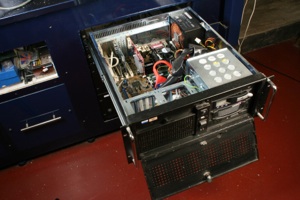
The computer running my mill is dedicated to that task and is built into the cabinet for the mill. It comprises an ASUS P4P800E motherboard (now obsolete) with 8Gb ram, a separate video card and a separate card for the parallel printer port. This is much more memory than is required, of course, but effectively means there is no practical limit on what I can do with the machine, for CNC tasks involving Mach3 or other control software I use. When not using Mach3, I can also run other CAD and CAM programmes with ease, and simultaneously, if I wish. I tend not to do that, preferring to run them on a separate machine, elsewhere; but the capability is there, for a small additional cost. The computer is built into a rack mount box, and has two removable hard disk drives so that I can swap from Windows to Linux and from one version of Windows to another. Totally unnecessary, but quite handy.
Jitter and latency
All computers are not the same, and different models of motherboards vary in performance. The issue is the extent to which Mach3 can send out signals in near-real-time. Latency refers to the time delay introduced as signals pass through a system. A slight delay may cause an error in positioning the cutting tool. Where latency is constant, some of its effects can be offset.
Jitter, on the other hand, is a much more serious problem because it is the variation in the rate of signals in what is supposed to be a constant stream. Unlike latency, jitter varies over time, so is less predictable. In machining, jitter can affect surface finish, as the slides speed up and slow down when they are supposed to be moving at a constant speed.
Latency is related to jitter, but while latency might be fairly constant, meaning the delays are relatively constant and the whole program (or sections of it) just send out signals a bit late, jitter refers to the extent to which individual signals in a stream vary from a uniform rate, resulting in one signal having a different latency than the next, in an unpredictable way.
Measurements show clearly that there is considerable variation in latency and jitter from one model of computer to another. This is important, and it needs to be dealt with when setting up Mach3 and the stepper driver hardware.
Interfaces
The computer needs to control the stepper motors or servos, and it does this by sending a set of signals which normally take the form of a train of pulses to control the steps, and a signal to control the direction. These are normally referred to as step-direction signals. The signals coming from the computer have no real power, and are at a much lower voltage than the steppers require. In addition, the steppers actually require something more complex than a train of pulses, because the coils inside the stepper motor need to be turned on and off in a particular sequence. So; we need to send the step and direction signals from the computer to some drive electronics (the stepper controller) which generate the appropriate sequence of signals to the stepper coils by taking account of the direction in which the stepper has to turn, and alter voltage and current levels to make the stepper motor turn.
Connect one side of the drive electronics to the computer, the other side to a stepper motor, and feed the power supply to the drive electronics. Step and direction signals from the computer are turned into appropriate high voltage and high current signals which are fed to the stepper motor to make it turn in sympathy with the step and direction signals. Easy really, if you are an electronics engineer; a useful black box if you are an ordinary mortal.
Some folks recommend that the computer is connected to a breakout board. There are some good reasons for this:
-
 a breakout board gives some protection to the computer, by isolating the computer’s outputs and inputs from the higher voltages used to drive the stepper motors or servos.
 -
a breakout board can simplify the physical connections between the printer port and the stepper/servo drive electronics. This was the original meaning of the term “breakout”, where the connections for the various signals associated with the parallel port can be made on larger, more human-friendly connectors on the breakout board. If soldering is not your forte, this is a significant simplification, as most connections can be made using screw-down connectors.
-
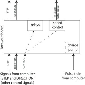
some breakout boards provide additional safety features, notably a charge pump. When Mach3 runs, it can be instructed to send out a continuous stream of pulses and the charge pump will allow the breakout board to operate while it is receiving those pulses. If the pulses from Mach3 stop, the breakout board will recognise this as a fault and will stop sending out signals to the stepper drive electronics, effectively stopping the machine.
-
some breakout boards provide relay outputs for switching things like coolant pumps or vacuum extractors. This can be done without a breakout board, but, again, it is conveniently done using the handy connectors on the board.
-
some breakout boards simulate a second parallel port or a dedicated port for an external motion controller. This can be important.
-
some breakout boards incorporate a speed controller so that Mach3 can not only turn on the motor for the mill spindle, but can control its speed. This is a very useful facility.
Here’s the signal path through a typical breakout board:
There are, however, some reasons not to use a breakout board. There have been some complaints that some breakout boards introduce a delay in processing the signals from the computer before onward transmission to the drive electronics (i.e. they have built-in latency). Buying a breakout board from abroad is not a great problem via the internet, to be sure, but postage and import taxes add considerably to the cost.
Motion Controllers
In recent times, new devices called motion controllers have appeared:
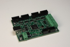
These solve two significant problems. The first is jitter, and the second is the problem of increasing numbers of computers which do not have parallel printer ports.
They also solve the problem of computer performance and processor speed limiting the performance of a CNC machine.
On a Windows computer running Mach3, a good motion controller largely eliminates jitter, and sidesteps the issues related to the speed at which the computer can send signals out of the parallel port by eliminating it entirely and acting as a substitute for the parallel port. Some motion controllers are mounted internally, inside the computer, as plug in cards, but the most popular choice for Mach3 is an external motion controller which connects to the computer via the USB port. This provides an ideal solution for a laptop.
The computer sends signals out of the USB port to the motion controller, and the motion controller sends signals to the stepper/servo drive electronics. Because the motion controller deals only with creating and sending the appropriate signals to the drive electronics, it can do this in real time, at high speed, bringing significant benefits. On the computer, the OS and the kernel attempt to deal with lots of other tasks at the same time, to move information around the computer, deal with the keyboard and a host of other tasks, which introduces unwanted and variable delays leading to jitter, and tends to slow the operation of Mach3. This limits the speed of machining, and means that the motion of the axes tends to be slightly variable, and the results of that may be visible in the surface finish as the feedrate of the tool varies slightly.
Here’s how signals are routed from the computer through the motion controller to the stepper motors or servos:
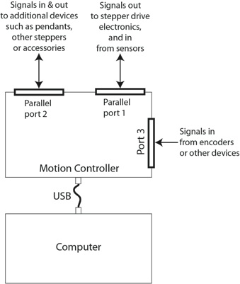
A Motion Controller like the SmoothStepper comes with a driver which is easily installed on the computer. That redirects signals from Mach3 intended for the parallel port, and sends corresponding signals to the SmoothStepper via the computer’s USB port. Although these are a recent development, motion controllers provide an effective way of controlling a CNC machine. It’s a good solution, but note that while some motion controllers work with LinuxCNC, SmoothStepper does not yet offer the required drivers.
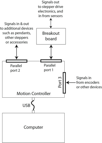
Some breakout boards combine the best of both worlds as they now incorporate ports designed for connection to a motion controller. This allows the breakout board to offer additional connectors for relays etc. Here’s the signal path when using both a motion controller and a breakout board:
Software
The primary requirement is for software to take instructions required to move the Controlled Point along a particular path and turn those into electronic signals for stepper motors. That’s Mach3.
If that is the only software package you use, you will be able to do quite a lot of fairly straightforward CNC machining on a wide range of workpieces. If you are a good programmer, you will be able to do a bit more, but there are limits, and Mach3 on its own is not enough to really make the most of CNC machining in the home workshop.
In a full CNC system, there are three kinds of software.
CAD software
Computer-aided design (CAD) software is used to create a design in 2 or 3 dimensions. All workpieces in the real world are 3 dimensional, but many machining operations mainly involve movements of the Controlled Point in 2 dimensions, so although many modern CAD programs can produce designs in 3D, this is not helpful for most milling operations, because the format of the data (information in computer-readable form) from 2D and 3D designs is fundamentally different, which causes problems in later stages of the process when the data is translated into movements of the slides.
Movements in 2 dimensions (usually X and Y movements of the slides) combined with a vertical depth of cut are termed 2D because once the cutter has reached its depth of cut, that does not vary, and there are no simultaneous co-ordinated movements of X and Z or Y and Z. Where the depth of cut is varied as X and Y movements take place, this is termed 2½D and this allows the creation of “low-relief” shapes which can be thought of as a kind of restricted 3D because it allows, say, a flat map of a landscape to be produced, with X and Y movements as well as enough control over the Z axis to produce the height-related features of the mountains or the valleys and rivers. 2D machining produces shapes with vertical sides to the cuts, whereas 2½D machining can produce pockets and raised areas on the work which are not restricted to having vertical sides. So 2D and 2½D machining covers the vast majority of what is required in the home workshop. True 3D machining is a rather different animal, and is outwith the capability of home machinists, at present. How, for example, could you machine a fully 3D object? Imagine machining a sphere containing a contoured map of the world, with the mountains, continents, oceans and rivers. How could you hold the workpiece so that this could be done in one work setup? How could you machine the “underside”? The most likely practical solution on a conventionally constructed mill would be to use multiple work setups in which you set up a block of material and machine part of it, then change the position of the workpiece and machine the next part, and so on. That is not 3D machining; it is a series of 2½D machining operations. We will deal with the challenge of machining 3D objects, in this series, but you should be aware that this will involve techniques to allow 3D objects to be created using 2D and 2½D machining techniques on a conventional mill, and that will involve specific work-arounds. In practice, we will use 2D machining for lots of workpieces, and 2½D machining for the rest.
CAM software
Computer-aided Machining (CAM) software is used to turn the features of a finished design into a set of instructions for a CNC machine tool. Normally, this will involve working with information from a CAD program, but the same process can be carried out with a manually-created design, although this is neither as convenient nor as efficient, and anything other than the simplest of shapes is better dealt with by using CAD then CAM techniques. Because the CAD and CAM stages of the process are so closely linked, some programs combine both functions, and some of the software we will use in this series of articles do just that. These are essentially CAM programs which incorporate CAD capability. A dedicated CAD program may have more sophisticated drafting capability, but that is not always required for designs of low or medium complexity, so a combined CAD/CAM program is a way of coping efficiently with the majority of designs.
A CNC program then uses the output of the CAM program to carry out machining to produce the finished object. The output of the CAM program needs to be prepared differently for each specific CNC program, so it is important that the CAM program has that capability. The general nature of CAM programs means most can output data in a range of formats suitable for a corresponding range of specific CNC programs. Because Mach3 is such a widely used program, most good CAM or CAD/CAM programs can output data in the form required by Mach3. In fact, most can output in more than one form for Mach3, depending on how you, as the user, want Mach3 to behave. Many can also output data in a form suitable for LinuxCNC (although some still refer to that software as EMC or EMC2).
In the full CAD/CAM/CNC cycle, it is essential that the data passing between the programs used at each stage of the cycle is in a form which each can recognise and use. If you are using a separate CAD program, for example, it needs to be able to output finished designs in a standard format which the following CAM program can read and use. This is where most free or low cost CAD programs fall down, and are not of practical use in a CAD/CAM/CNC system. The basic requirement is that a CAD program must be able to output data in a standard DXF format. This is Autodesk’s longstanding AutoCAD file format which has become a universal standard. There are various versions of this, but most CAM programs can cope with many of these, so this is the standard format we must look for. This also means that you can take a DXF file from elsewhere, such as one prepared by someone else, and use it in your CAM program, allowing you to machine an object using a file obtained from elsewhere. This is important, as it means you do not always need to design a workpiece yourself, but can still machine the object.
Some CAM programs can also accept other file formats for 2½D designs from other software packages such as AutoCAD, RhinoCAD, TurboCAD, and many others.
Combined CAD/CAM programs automatically deal with data transfer, which takes place inside the program with no need for the user to do anything about this. That’s a bonus, of course.
CAD software of considerable power is available from a number of sources, in all the usual forms: free, low-cost, and high-end packages, so you can choose how capable you want the software to be, whether you want to design in 2 or 3 dimensions, and how much you want to spend. As always, you get what you pay for, but there are some exceptions, with some good software available under the GNU or GPL General Public Licence system.
There are some fundamental differences between 2D and 3D design programs, and a noticeable difference in the way you might approach the design task if you are using 2D or 3D software. The current tendency, industrially, is to use 3D software such as AutoDesk’s Inventor or the 3D version of the old favourite AutoCAD (which takes the form of 3D capability within the basic 2D AutoCAD), RhinoCAD 3D, TurboCAD 3D and any of many others. These are hugely capable programs, but they come at a considerable cost, and they output files in a format which not only differs from the standard 2D formats but requires a different CAM program to prepare for machining. We will consider machining designs prepared in a 3D CAD package separately, later. It’s an interesting challenge but has its own particular requirements.
CAM software has evolved over the years, and most is now integrated as part of a CAD/CAM package. Some high-end packages such as EdgeCAM are specifically tailored to provide efficient machining paths for the Controlled Point, and do that job very well. Some low cost or free CAM packages exist and are particularly useful for specific machining tasks like milling circuit boards, but, again, the tendency is to add CAM capability to existing design programs. GSimple is a typical free CAM program, developed by an enthusiast and quite capable within specific limits. It cannot deal with DXF files containing “blocks” for example. Nor can it machine islands within pockets. For some workpieces, those are serious limitations.
FreeMill is a free 3D milling package capable of importing 3D files in specific formats such as VisualMILL, STL, Rhino .3dm, VRML and Raw Triangle . It has been created by a commercial company, but is provided free using a well-known model in which good software if provided free to (a) entice you to pay for training, and (b) entice you to upgrade to the full commercial product. This works well for end-users who can read the manuals and who do not need the full commercial product.