CNC in the Workshop


Backlash
Before we rush off and cut metal, we need to deal with some important matters, beginning with backlash. On a perfect machine, there would be no backlash in any of the feed screws, so giving a command to move from one point on an axis to another would always result in the Controlled Point (CP) arriving exactly at the second point. Backlash is often present in the real world, though, largely because of necessary clearance between the flanks of the lead screw nut and the lead screw itself.
There are some very sophisticated ways of dealing with backlash, including screw mapping of the leadscrews to account for variable backlash along the length of each leadscrew, but, on this page, we simply deal with the basic approach to backlash compensation.
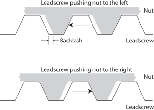
The figure opposite shows a cross-section through the nut and the lead screw. In the upper diagram, the flank of the thread of the lead screw is pressing against the thread in the nut, pushing the nut to the right. There is a little clearance between the rear flank of the lead screw thread and the following face of the thread in the nut, and that results in backlash. If the rotation of the nut is reversed, the lead screw will rotate a little without the nut moving, until the rear flank of the lead screw has taken up the clearance and can press against the mating face of the thread in the nut.
Jogging
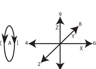
If we talk about “running” a program, maybe “jogging” makes sense as a slower movement. Jogging refers to moving the Controlled Point (CP) a little at a time, under keyboard control. Mach3 uses the numeric and symbol keys to move the X, Y, Z and A axes, as shown in figure on the right, but it also incorporates some jogging controls on screen which are not replicated in the keyboard.
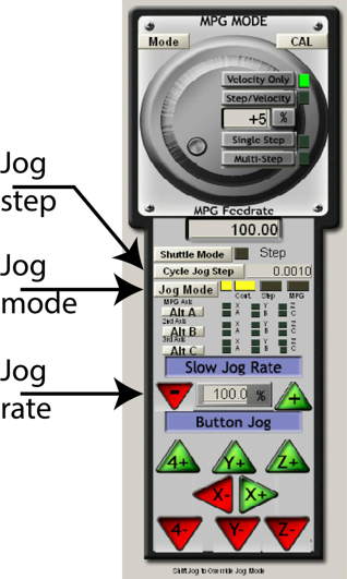
Jogging is a frequently used facility, but the jogging screen is hidden, and you may want to write a sticky note and paste it to your monitor to tell you that:
Pressing the Tab key reveals the jog controller for each of the four axes.
Press Tab now.
If you have ever sat in a railway carriage next to another carriage on the adjacent line, you may have experienced that strange sensation where it seems as though you are moving, when you are actually stationary and the other carriage is moving. You are about to replicate that, so watch closely. Although jogging moves the slides on the mill, its purpose is to move the Controlled Point in relation to a workpiece which is secured to the table. So focus on what the CP is doing, in relation to the axis being jogged. Imagine the CP was moving, and the slides were stationary. The slides are stationary, as far as the workpiece is concerned, and the CP is moving in relation to that workpiece. It’s just your eyes that are deceiving you; but don’t get in the way of a slide, otherwise you will become even more confused when it hits you and you realise that although you are standing still, you are moving in relation to the slide and the workpiece.
The computer will respond to commands from what has come to be known as the G Code language. This is a bit of a misnomer, but it’s the term everyone uses, so it will be good enough for us. G Code commands consist of a letter (usually G, but may also be M, S, F or O, depending on what we trying to instruct the machine to do) followed by a number, and may then be followed by other terms.
The G0 command is used to move the CP at rapid rate, and it takes the form:
G0 X~ Y~ Z~ A~ B~ C~
The ~ character is the “tilde” character, and it is used to signify that when the command is entered, there should be a number in this position, so you would never type the command exactly as it appears above.
The letters X, Y, Z, A, B and C denote the axes, up to 6 of them, but you would only include those you required for a particular command. Most mills will have X, Y and Z axes under computer control. Many, but not all, will have a fourth axis (usually a rotary axis) A. Very few will have B or C axes.
So typical G0 commands will look like:
G0 X100 Y20 Z40
G0 X-20 Y10 Z-0.02 A120
The numbers will vary depending on the position to which the CP is to be moved. Axes which are not listed after the G0 command will be ignored and the CP will not move in relation to those commands. For example:
G0 X70
will move the CP along the X axis only, to position 70. The position of the CP in relation to all the other axes will remain unchanged.
We are about to make some moves. Some of you will be working on small benchtop machines, like the little Sherline, while others may be working on a Bridgeport with a much larger table and a greater range of movement of the head. I don’t know which machine you have, or where you have set HOME, so it is your responsibility to check whether a given move will be too large from your machine, or whether a cutter will hit an obstruction, BEFORE you use a command. This is a general rule, whether you are following the commands in these articles or using your own commands. Check before you carry out a move. It’s a bit like the old adage “measure twice; cut once”; it’s good practice and, given the cost of cutters which may snap, or the potential cost of rectifying damaged machine parts, it’s a wise precaution. Experience suggests you may need to accept that mistakes happen from time to time, so practice saying “Ah well…” in a calm and measured manner; and keep that soothing mug of tea handy.
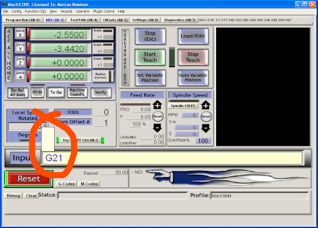
From now on, all units are metric. If you are using inches, just divide the numbers by 25. I can no longer think in inches; I let it go when education went fully metric, in 1965. Even if you are determined to think imperially, I suggest you work in millimetres temporarily, by making sure the cursor is in the MDI input window then typing G21 and pressing the RETURN key. The G21 command makes Mach3 treat all distances as millimetres. When you want to use inches, type G20 and press RETURN.
My STRONG advice is to work in millimetres if you are following the articles on this site. Then we will not get confused. You could use the numbers as inches, but that would mean some of the movements would be much larger than your machine could cope with. Internally, Mach3 doesn’t care what units are used. It simply moves a number of steps per unit. But for us humans, it helps if we call the units millimetres or inches, so that we can relate movement to distances that mean something in the real world.
To make a rapid move to X50, enter G0 X50 into the MDI input box then press the RETURN key. (I will not repeat the instruction to press the RETURN key to actually carry out a typed command; just take it as read from now on.) . That should result in the CP moving to the position where the X co-ordinate is 50. This is an absolute position in relation to the HOME position where X=0. Let’s just test this is what has happened.
Enter G0 X0
then G0 X50
then G0 X50 again.
The CP should have moved back 50 units to where the X DRO on-screen reads 0.
Then it should have moved to where it read 50.
Finally it should have remained at X50 without moving.
If it moved to X100 and the X DRO reading is now 100, the CP is moving relative to the last position, rather than moving to an absolute co-ordinate position. Fix this by going to Config > General Config then looking in the second column, about half way down, for the Distance Mode box. Click in the Absolute radio button. While you are there, make sure the adjacent box “IJ Mode” is set to INC. Click OK. Then jog to a suitable position, zero the DROs, and try the movement test again (from the beginning of this paragraph). Incremental movement is useful, in some circumstances, but is not useful at this stage. Let’s walk before we run.
The feed rate for the G0 rapid moves is set by Mach3 when it starts up, and was stored in a file created when you set up your stepper motors by following the instructions in the Mach3 manual (section 5.52). At this stage, it doesn’t much matter what that speed is, but if it seems dreadfully slow, go back to the setup procedure and increase the speed. I set mine to maximum. You will also notice that the G0 moves begin with a period of acceleration and end with a period of deceleration. If those take too long, make the initial and final slopes on the display shown in 5.5.2 steeper. Realistically, the slides cannot accelerate from stationary to full speed in no time at all, because of inertia, and the acceleration rate will depend on the power of your stepper motors as well as the gearing between stepper and leadscrew. The important thing is that the movement of the slide keeps pace with the speed of the stepper as it accelerates and decelerates. Suck it and see.
G0 X0 Y0 Z0 takes you back to the Home position. Y and Z were probably still at their 0 positions, but stating where we want each axis to be as part of the command is a simple way to make sure we end up where we want to be, as opposed to where we assume we will be. There is a general principle here, and it is always wise to specify where you want each axis to be, even if we are fairly sure that some of the axes are there already. Certainty is better than assumption.
Basic command moves
The next stage is to make the CP move in response to a typed command. A typed command which is to be carried out immediately is known as a Manual Data command, and the process is known as Manual Data Input or MDI, for short. You will use this kind of command frequently, and Mach3 has a specific facility for handling these commands. Amongst the Screen Switching Controls at the top of the Mach3 window (section 6.2 of the Mach3 manual, or see earlier screenshot) is the MDI button. Click it, or hold down the Alt key on the keyboard and dab (press and release) the 2 key (referred to from now on as Alt2). That should take you to the MDI screen. Note that if you are using the software from Arc Euro Trade, the MDI input bar is on the main Mach3 screen, so you do not need to press ALT2 to see it.
Click to put the cursor into the MDI input box (see figure on the right hand side). Strictly speaking, in computer terms, this is known as making the MDI input box the “focus”, and that is a generic computer term for clicking in any window or input box to make it active.
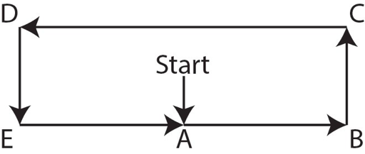
Now move in a rectangular path (see diagram above):
G0 Y-30
G0 X100
G0 Y30
G0 X-100
G0 Y-30
G0 X0
G0 Y0
Those commands changed only the values which changed between positions, and where X or Y did not change, they were not mentioned in the command. Mach3 only changed the values indicated by the X or Y.
So far; so good.
Go back to X0 Y0.
Of course the movements can be a bit more complex. Here’s a path a bit like a sharp figure 8 lying on its side:
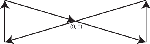
G0 X100 Y-30
G0 X100 Y30
G0 X-100 Y-30
G0 X-100 Y30
G0 X0 Y0
Those commands specified the X and Y values of each point, even when one of those values did not change. It is easier to read and understand those commands, although it takes more typing.
And more complex still:
G0 X0 Y-30 Z50
G0 X100 Y30 Z50
G0 X-100 Y-30 Z10
G0 X-100 Y30 Z10
G0 X0 Y0 Z0
Here, the points on the path were fully specified in 3D space. This makes it very clear where the CP is to be, in 3 dimensions. This is always my preferred method, even if it involves a bit more typing. It is much easier to look at any line in the program and understand where the CP is supposed to be. That’s another good principle: make your programs readable, so that when you return to a program later, you can understand what the program does. Memory is a wonderful thing, but I find that, as time passes, it is not always 100% reliable.
Cutting feed rate
G0 is a rapid move and is intended for moves which take place without cutting, as positioning moves, usually in preparation for a subsequent cutting operation.
G1 moves are at cutting feed rate (mm/minute or inches/minute); otherwise, it behaves just like the G0 command. The speed of movement for a cutting command is set by the F command (F being short for Feed) which takes the form F~ where ~ will be a number. The units are whatever units Mach3 has been told to work in; so if you are working in millimetres, F 100 would set the speed to 100mm/min. If you were working in inches, F100 would set the speed to 100 in/min.
The best place to put an F command is on a line before a cutting move, as that is easiest to see and understand if you are looking back at a set of instructions, e.g.
F100
G1 X75 Y20
but you can put the commands on the same line, in any order, and they will have the same effect. I find that a bit confusing, and not at all easy to read, but you need to know this for later, when we come to read programmes generated automatically by other software. So, the same effect can be achieved by typing
F100 G1 X75 Y20
or by
G1 X75 Y20 F100
Useful feed rates depend on the material being cut, the cutter being used, and the rigidity of the machine, but I have often found that a conservative feed rate in the range 25 to 100 mm/min is a useful place to start, for metals. More on feed rates on a separate page.